background image

Pilot clutch

128

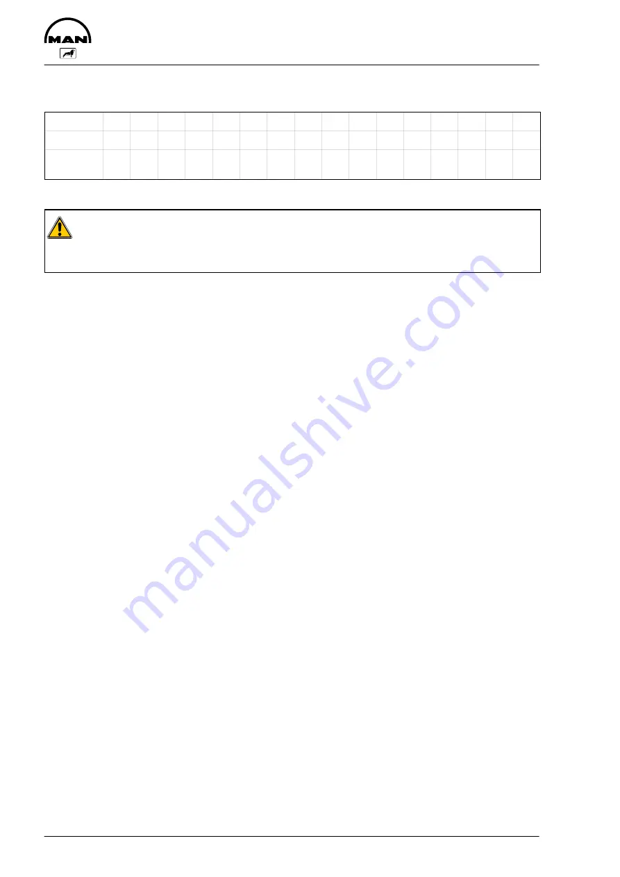
Wear limits for the friction disk and friction ring above which

it is advisable to replace these components

Type

005 010 020 030 035 040 045 050 055 060 065 070 075 080 085 090

Thickness

3

3

3

4

4

4

4

5

5

6

6

6

7

7

8

8

Permissi-

ble wear

0,3

0,3

0,3

0,4

0,4

0,4

0,4

0,5

0,5

0,6

0,6

0,6

0,7

0,7

0,8

0,8

Caution:

All front-mounted clutches are balanced with a balance quality of Q = 6.3!
If running after repairs is not smooth the clutch must be rebalanced with the limits contained in
the assembly drawing.

Balancing

All front-mounted clutchs are balanced with a balance quality of Q = 6.3! In the production of new parts in
our company the parts are well below the permissible limits. The wearing parts to be replaced in the event
of a repair are rotationally symmetric and experience has proven that they do not lead to an impermissible
or disturbing imbalance.

If contrary to expectation running is irregular the balancing must be checked. The assembly drawing is to
be referred to for the permissible imbalance data.

Summary of Contents for D 2866 LUE 605

Page 1: ......

Page 2: ......

Page 3: ...pert knowledge necessary for handling Diesel engines was taken for granted when this publication was compiled Any repair of components such as injection pump alternator etc ought to be left to our or...

Page 4: ...parts with different rates of linear expansion under heat e g aluminium and cast iron and leaks may then occur Example the cap of the front crankshaft seal If a sealing agent or an adhesive is used h...

Page 5: ...g and installing engine water pump 41 Repairing engine water pump D 2866 LUE 602 43 Repairing coolant pump with high temperature and low temperature parts D 2866 LUE 605 48 Cleaning cooling system 55...

Page 6: ...g pistons with conrods 112 Removing pistons from conrod and fitting checking replacing conrod 115 Removing and installing replacing piston rings 117 Replacing cylinder liners 119 Measuring piston prot...

Page 7: ...602 605 D The D at the start of the type classification stands for diesel 28 The numbers 28 indicates that the power plant in question has a bore of 128 mm 6 The 6 means 160 mm stroke This figure is...

Page 8: ...rised persons D The engine must be started and operated by authorised personnel only D When the engine is running do not get too close to revolving components Wear tight fitting working clothes D Do n...

Page 9: ...ine MAN parts only Installation of equally good parts from other suppliers may cause severe damage for which the workshop carrying out the work is responsible D Never operate the engine while it is dr...

Page 10: ...h hazard if the basic safety and hygiene related regulations are observed Health and safety regulations D Avoid prolonged excessive or repeated contact of old engine oil with the skin D Use a suitable...

Page 11: ...relation to the values measured on commissioning the engine D Power D Exhaust temperature D Coolant and lubricant temperature D Oil pressure and oil consumption The following criteria greatly influenc...

Page 12: ...and its causes If engines are not pressurised the risk of premature damage to bearing surfaces is very high because it takes a relatively long period of time for the lube oil drawn in from the oil pa...

Page 13: ...or from crankcase bores which may not be plugged can be detected immediately For this purpose mount the engine on an assembly dolly remove the oil pan and install a suitable oil collector under the cr...

Page 14: ...Notes 12...

Page 15: ...e probable causes and in vestigate and eliminate these successively on the basis of the table and your own experience This helps to reduce repairs to the required scale and to counteract claims regard...

Page 16: ...arter starter interlock relay defective carbon brushes worked loose worn winding defective short to ground x x x x Engine oil viscosity unsuitable not suitable for ambient temperature lubricating oil...

Page 17: ...x x x o Fuel high pressure system injection pump worn incorrectly set o x o o Fuel high pressure system injection pump constant pressure control valve re turn flow constrictor faulty x x x o x EHAB de...

Page 18: ...e speed control cannot be activated does not switch off engine revs too high 18 Fuel consumption too high 19 Lubricating oil pressure too low 20 Lubricating oil pressure too high 21 Lubricating oil co...

Page 19: ...Memoranda 17...

Page 20: ...Engine views 18 Engine views 3 4 2 1 7 6 5 8 11 10 9...

Page 21: ...Crankcase breather 3 Oil filter 4 Turbocharger 5 Flame starter sheathed element glow plug 6 Solenoid valve for flame starter 7 Electro hydraulic cutout EHAB only D 2866 LUE 602 8 Oil drain plugs 9 Pil...

Page 22: ...for oilcooler 13 Oil suction pipe 4 Bore for injection pipe lubrication 14 Spray nozzles for piston cooling 5 injection pump 15 Bore for main bearing lubrication 6 Bore for oil cooler 16 Bore for thr...

Page 23: ...02 3 4 3 1 2 5 6 7 8 9 10 11 1 Flame starter sheathed element glow plug 7 Hand pump 2 Soleniod valve 8 Fuel filter 3 Injection pump 9 Fuel supply from tank 4 Fuel return to tank 10 Fuel pre filter 5 L...

Page 24: ...ystem Schematic diagram D 2866 LUE 605 1 2 5 3 3 4 9 8 7 6 1 Flame starter sheathed element glow plug 6 Tank 2 Solenoid valve 7 Fuel pre filter 3 Injection pump 8 Hand pump 4 Fuel return to tank 9 Fue...

Page 25: ...Diagram 23 10 9 8 7 6 5 4 1 3 2 1 Surge tank 6 Retarder oil cooler 2 Positive pressure negative pressure valve 7 Thermostat 3 Coolant filler neck 8 Water pump 4 Thermostat 9 Oil cooler 5 Radiator 10 E...

Page 26: ...Engine management schedule 24 1 2 3 4 6 5 1 Oil pump impeller gear 4 Injection pump drive gear 2 Oil pump drive gear 5 Idler gear 3 Crankshaft gear 6 Camshaft gear...

Page 27: ...is another scale engraved on the flywheel which can be read through an inspection hole in the flywheel housing but access may be difficult The scale should be used for readjusting the pointer after th...

Page 28: ...ns of the following special tools 1 Light signal transmitter Fig 6 Push light signal transmitter into socket in gover nor housing Ensure that the lug fits in the groove Tighten the knurled nut by hand...

Page 29: ...lso be achieved with a plug in sleeve The sleeve is to be made of aluminium or steel Set engine to start of delivery as described above Insert the sleeve into the governor housing up to the stop The s...

Page 30: ...head cover from cylinder no 6 flywheel end When the values of this cylinder are in crossover the piston in cylinder no 1 is at ignition TDC Remove screw plug from governor housing see Fig 5 The deliv...

Page 31: ...ch escaping fuel in a suitable contai ner Fig 3 Remove holders from injection pump Unscrew the mounting bolts from the injection pump flange Take off injection pump Note Ensure meticulous cleanliness...

Page 32: ...Remove the mounting bolts from the injection pump drive gear so that it can be turned in the slots Hold the injection pump camshaft in place while turning the gear Fit a new O ring lightly oiled on t...

Page 33: ...el injector using a pin spanner Fig 3 Screw adapter on to nozzle holder Screw on inertia extractor and knock out nozzle holder Take sealing ring off the injection nozzle Check and repair injector see...

Page 34: ...ide of the pressure screw to the threaded portion of the pressure screw and to the nozzle holder see shaded area Fig 6 Fit fuel return line together with new sealing rings to the nozzle holders and ti...

Page 35: ...ure deviation insert a differ ent shim If the pressure is too low insert thicker shims if it is too high insert thinner shims The initial tension of the compression spring de creases if a high number...

Page 36: ...nd petrol or Diesel fuel Clean nozzle needle with a clean cloth Clean coked nozzle needle surface on lathe with a piece of wood not too hard dipped into oil Note To prevent corrosion do not touch lapp...

Page 37: ...ghtening it to the specified torque see Service Data Check injector on the manual test stand Ensure that the edge type filter is correctly seated in the injector body Fig 9 A dislocated sieve bar filt...

Page 38: ...ection pump can be heard to open D Screw in and tighten the hand pump plunger D Start the engine D Check the fuel prefilter for leaks Cleaning fuel pre cleaner D 2866 LUE 605 Strip the fuel pre cleane...

Page 39: ...s dange rous waste and must be disposed of ac cordingly Bleeding the fuel system Note To bleed the fuel system switch on the ignition so that the EHAB will be open An arrow on the filter head indicate...

Page 40: ...heathed element glow plug with Hylo mar until it stops at the counter nut and align it with fuel line Connect up fuel line and electric connection Tighten counter nut Checking solenoid valve for leaks...

Page 41: ...of drinking water from the mains and anti freeze based on ethylene glycol and or anticorrosion additive See Publication Fuels Lubricants and Coolants for MAN Diesel Engines Coolant must be poured in a...

Page 42: ...s follows D Suspend the thermostat in a bowl of water D Heat up the water D Using a suitable thermometer ascertain the start of opening and compare it with the setpo int value in Service data D If nec...

Page 43: ...ater pump D Draining off coolant see page 39 D Remove the thermostats see page 40 Take V belt off see page 125 Fig 1 Remove V belt pulley Fig 2 Remove the mounting bolts from water pump and take off w...

Page 44: ...permits small amounts of coolant to pass through it This coolant passing through results in a trace of drained coolant below the drain bore The water pump need not be exchanged or repaired because of...

Page 45: ...6 Hub 7 Circlip Remove water pump see page 41 Disassembling water pump Fig 2 Clamp the water pump in a vice use protective jaws Pull off V belt pulley with three arm puller Fig 3 Unclip the circlip fr...

Page 46: ...ce Use a suitable mandrel to press the water pump shaft together with bearing out of the housing Shaft and bearing are encapsulated and replaced as a single unit only Take off axial face seal Assembli...

Page 47: ...l on page 47 Note The seal can be exchanged even without removing the water pump shaft Fig 10 Slowly press impeller on to bearing shaft to ensure correct gap Fig 11 For this purpose an inspection hole...

Page 48: ...e special tools see chapter Special tools and proceed as follows D Align guide ring with the two dowel pins on the pump housing D Insert pressing ring into guide ring D Place a flat steel min thicknes...

Page 49: ...n note for mechanical seal Fit the mechanical seal wet i e when fitting coat holding sleeve and coolant pump shaft with a mix ture of 50 water and 50 cleaning spirit or 40 to 50 antifreeze as per MAN...

Page 50: ...oolant pump HT circuit 8 Mechanical seal 51 06520 0099 9 Counterring complete 51 06520 0100 10 Impeller for coolant pump LT circuit 11 Splash shield 12 Mechanical seal 51 06520 0096 13 Water pump bear...

Page 51: ...ed bores M8 are provi ded Fig 7 Note Remove bolt from low temperature part Fig 1 item 5 Align water pump housing on a suitable and stable surface Use a suitable mandrel to press the water pump shaft t...

Page 52: ...to bearing shaft Fig 10 Turn water pump housing over Press in new me chanical seal with press fitting sleeve special tool until it stops Observe installation note for seal on page 47 Fig 11 Press in...

Page 53: ...e special tool until it stops Observe installation note for seal on page 47 Fig 14 Lay coolant pump gasket on pump housing Fig 15 Carefully fit low temperature suction part to high temperature pump ho...

Page 54: ...on using special tool Fig 17 Press in new mechanical seal pos 6 with press fitting sleeve special tool until it stops Observe installation note for seal on page 47 Fig 18 Slowly press impeller on to b...

Page 55: ...21 If no suitable pressing tool is available you may use self made special tools see chapter Special tools and proceed as follows D Align guide ring with the two dowel pins on the pump housing D Inser...

Page 56: ...nstallation note for mechanical seal Install mechanical seal while wet i e to install it coat holding sleeve and water pump shaft with a mixture of either 50 water and 50 cleaning spirit or 40 to 50 a...

Page 57: ...ti freezing agents and corrosion inhibitor or defect not early enough replaced covers for filler neck and working valves If twice in a short time the water pump of an engine develops leakes or the coo...

Page 58: ...bottom edge as otherwise foaming will cause the pickling fluid to spill over Damaged tube bundles may develop leaks when dirt deposits are removed Filler caps and working valves of cooling system The...

Page 59: ...ing and filter insert are filled with hot oil danger of burns and scalding Reinsert oil drain plug with new gasket Fig 2 Loosen the securing bolt of the filter cup Remove filter cup and clean inside F...

Page 60: ...that the oil does not overflow Danger The oil is hot risk of scalding Do not touch the oil drain plug with bare fingers Oil is an environmental hazard Handle it with care D Draining off coolant see pa...

Page 61: ...Fig 5 Take a new o ring for oil cooler housing Screw on oil cooler housing together with attached oil cooler Fig 6 Tighten the securing bolts with the prescribed tor que D Attach oil filter with new s...

Page 62: ...ensure that the oil does not overflow Danger The oil is hot risk of scalding Do not touch the oil drain plug with bare fingers Oil is an environmental hazard Handle it with care Fig 2 Remove EHAB cran...

Page 63: ...emoving and installing the oil pan 61 Fig 5 Fitting the EHAB crankcase breather and oil filler neck Refit oil drain plugs with new seals Fill up the engine oil Check oil level Check the oil pan for le...

Page 64: ...n pipes Measure backlash between oil pump drive gear and crankshaft gear and compare value with the nominal value Replace worn gears Fig 2 Remove pressuer relief valve Opening pressure see Service Dat...

Page 65: ...d pump housing for wear Fig 7 Remove the oil pump drive gear To do this lay the pump on a suitable surface and press off the drive gear with a mandrel To install place the drive gear on the shaft sup...

Page 66: ...Installing oil pump Fig 10 Before installing check whether the oil pumps runs smoothly and then fit them free of tension Fit oil suction line with seal in a tension free man ner Screw on pressure rel...

Page 67: ...hich are used as marker points for installing the nozzle in the event of repairs Checking oil spray nozzle valve Fig 3 Use a piece of wire to check whether the valve plunger is easy to move Opening pr...

Page 68: ...Memoranda 66...

Page 69: ...nk the engine to TDC This ensures that it is easier to fit the graduated disc during subse quent assembly work D Block the crankshaft drive D Relieve tension on the V belt and remove the belt D Remove...

Page 70: ...3 Loosen the securing screws of the cover Fig 4 Remove the cover Only replace the front crankshaft gasket as a com plete unit i e replace the bearing race and the radial shaft sealing ring Replacing b...

Page 71: ...The adapter must lie free of clearance on the crankshaft so that the right press in depth of the bearing race is ensured Pull the bearing race as far as it will go into the press in sleeve on the ada...

Page 72: ...of the scale disc relative to the cranks haft as you do so Tighten the securing bolts with the prescribed tor que Fig 12 Screw on delivery start indicator Tensioning V belt Fig 13 Therefore check whet...

Page 73: ...assembly clean all clutch parts see page 127 Push pre assembled clutch on to driver flange and fasten it with interior bolts 69 Nm Connect propshaft to clutch again and fit washer with bolts 25 Nm Po...

Page 74: ...el with suitable lifting gear Danger The flywheel is heavy Use lifting gear Fitting flywheel Fig 3 Insert the guide pins Coat the sealing face on the inside of the flywheel with Antipor 46 sealing com...

Page 75: ...contact surface of the starter motor toothed wheel prior to shrinking on the starter mo tor toothed wheel If the required value is exceeded replace the flywheel Engage the flywheel at the hub Apply th...

Page 76: ...ver to prise out seal Fig 2 Special tool for prising out crankshaft seal Installing crankshaft seal Fig 3 When fitting a new shaft seal you should also ex change the bearing race of the flywheel Inser...

Page 77: ...anged using a puller special tool Fig 2 Insert the new bearing race into the pressing man drel special tool so that for the subsequent as sembly the internally chamfered side faces the fly wheel Caref...

Page 78: ...eals Even the slightest damage to the seal would result in leaks The sealing lip and the race of the flywheel must not be coated with oil or any other lubricants When installing a new seal always repl...

Page 79: ...plug to sole noid valve and to temperature sensor Unscrew and remove fuel pipes to solenoid valve and sheathed element flame glow plug Fig 2 Remove connection to turbocharger Fig 3 Remove the mountin...

Page 80: ...rodu ced by MAN The exhaust gas pipe can be removed with the exhaust manifold attached Remove the heat shields Installing exhaust manifold Fig 2 Before fitting the exhaust manifold screw in 2 stud bol...

Page 81: ...ent for a satisfactory level of engine power is setting in accordance with regulations start of fuel delivery and of the valve clearance speed adjustment pedal value The following must also be checked...

Page 82: ...non permitted inclines Excessive crankcase pressure e g due to defective oil separator valve crankcase breather or piston ring wear Compressor coking At permanently high charge air temperatures e g c...

Page 83: ...ge air pressuer No generally applicable target value for charging pressure can be given as the installation conditions exert an influence The target value is the value determined on commissioning of t...

Page 84: ...rger Fig 1 Detach bleed pipe leading to cylinder head cover of cylinder 6 and oil return pipe from turbo charger Fig 2 Then detach the pipe to the crankcase breather and the oil pressure pipe Fig 3 Re...

Page 85: ...dies Installing turbocharger Fig 6 The turbocharger is fitted in reverse order On assembly new gaskets and new self locking nuts are to be used Before connecting the oil supply line fill the bea ring...

Page 86: ...on read off and note the value The difference between the values obtained is the axial clearance If the play exceeds the permissible value ex change turbocharger Radial clearance The radial clearance...

Page 87: ...screws Loosen mounting bolts of rocker arm bracket Remove rocker arm bracket Disassembling and assembling rocker arms see page 90 Removing cylinder head D Drain coolant see page 39 D Remove injectors...

Page 88: ...d blow out threaded bores in crankcase Clean sealing faces on cylin der head and crankcase Lay new cylinder head gaskets in place in dry condition ensuring that the holes match those in the crankcase...

Page 89: ...ht ening torque for mounting bolts 20 Nm If a steel ruler is not available mount exhaust manifold and tighten to 20 Nm D Tighten cylinder head bolts as specified D Remove steel ruler Installing the ro...

Page 90: ...ylinder head gasket Tighten cylinder head bolts while the engine is cold i e the crankcase is warm to the touch or colder Before inserting the cylinder head bolts apply engine oil to the thread not to...

Page 91: ...cker arms are relieved The valves of the synchronous cylinder are then in cross over Set valves in the cylinder 1 5 3 6 2 4 6 2 4 1 5 3 Valves are in cross over in cylinder Fig 3 I Vibation damper II...

Page 92: ...cker arm from rocker shaft Note If the rocker arm bearing bushes need to be replaced new or exchange rocker arms ready for fitting are to be used Fig 3 On fitting the rocker arms on the rocker shafts...

Page 93: ...ing a magnet D Move assembly lever upwards Caution spring under tension risk of injury and away to one side Figs 3 and 4 D Take off the upper spring plate the valve springs and the washer D Turn cylin...

Page 94: ...n even valve seat has been achieved Machine valve seat insert if necessary Turn cylinder head over and insert valve spring washers Screw off valve assembly lever Fig 6 Turn cylinder head over Place as...

Page 95: ...e cone pieces Use suitable tool to lightly knock back the valve springs to ensure that the valve cone pieces sit correctly Caution Ensure that the valve cone pieces sit cor rectly since valve cone pie...

Page 96: ...o the cylinder head using pressing mandrel and spacer sleeve special tool Fig 2 The valve guides vary only in length 1 Inlet 2 Exhaust 3 Press in depth see Service Data The correct press in depth is o...

Page 97: ...ne Fig 1 Use a valve seat machining tool valve seat lathe to cut an approx 3 4 mm wide groove in the valve seat insert Insert internal puller into the groove and tighten it Fig 2 Note To avoid damage...

Page 98: ...ides Note When the valve seat inserts have been changed the valve seats must be re worked Note D After temperature equalization machine valve seats D After machining clean cylinder head and check for...

Page 99: ...ple 13 Mains connection 14 Magnetic flange with coil 15 Guide pipe 16 Slewing arm Fig 2 Select suitable guide mandrel screw it in with a spanner 12 mm and tighten it Note For extreme precision work th...

Page 100: ...igorously and evenly but under no circumstances against the di rection of turning as otherwise the car bide cutting edge may break Fig 6 Once the valve seat has been expertly machined reduce the worki...

Page 101: ...lve retrusion If new valves and seat inserts are used increase the depth of the seat bore in the cylinder head ac cording to the amount of material removed from the cylinder head interface Fig 9 The v...

Page 102: ...asive paste Fig 3 The valve seat must have a faultless closed grind ing pattern The grinding pattern width is correct if the valve seat insert is in order 1 Valve tapered area 2 Valve seat Fig 4 1 Val...

Page 103: ...of starter until the pointer of the compression recorder is not de flected any further Connect up compression recorder with test con nection to the next cylinder and check all cylinders as described a...

Page 104: ...Danger The gear case is heavy Use lifting gear Remove the timing case gasket and fit a new gas ket Clean contact face on timing case and crankcase of sealing residues Fig 3 Check the contact washer o...

Page 105: ...arings in doing so Check the camshaft for wear and damage replace if necessary In the case of damage to the camshaft or drive toothed wheel the entire unit camshaft toothed wheel must be replaced Fig...

Page 106: ...t bearings 104 Fitting the camshaft Fig 4 Oil and insert the valve tappets Oil the camshaft bearing bushings Oil the camshaft and insert carefully Caution Do not damage the bearings Fig 5 In doing so...

Page 107: ...the valve clearance of the 1st cylinder cor rectly Fig 2 Turn the engine using the barring gear until the valves of the 1st cylinder overlap Turn the engine back to approx 50_ before TDC then turn for...

Page 108: ...the crankshaft bearing caps in stages from the inside outwards and remove Remove the bearing cover and place to one side in the order of installation Remove the bearing bush halves from the bearing c...

Page 109: ...the bearing surfaces of the bearing bushes and insert the crankshaft In doing so note the marking of the crankshaft and camshaft toothed wheel Fig 8 Check bearing cover bolts for max permitted length...

Page 110: ...ion and read off the clearance from the dial gauge D If the permitted axial clearance is exceeded fully replace the main bearing bushes Fig 10 Measure conrod bearings insert pistons with con rods Coat...

Page 111: ...ds and remove Remove the bearing cover and place to one side in the order of installation Remove the bearing bush halves from the bearing covers and place to one side assigned to the bea ring covers F...

Page 112: ...ponding repair level Fig 7 Oil the bearing surfaces of the bearing bushes and insert the crankshaft In doing so note the marking of the crankshaft and camshaft toothed wheel Fig 8 Check that the beari...

Page 113: ...e from the dial gauge D If the permitted axial clearance is exceeded fully replace the main bearing bushes Fig 10 Measure conrod bearings insert pistons with con rods Coat the conrod bushes with oil a...

Page 114: ...are numbered at the conrod foot place to one side ac cordingly arrage them in corresponding order Remove combustion residues oil carbon from top cylinder edge using a piece of hard wood Caution Do no...

Page 115: ...journals use bearing bush of the corresponding repair level Fig 6 Insert the bearing bushes in the conrod or conrod bearing cover Caution The rod shell has a red or yellow mark on the side The running...

Page 116: ...e side Fig 10 Screw in the conrod bolts and tighten them in sta ges to the prescribed value Final tightening according to rotation angle me thod tightening torques and reusability of bolts see Service...

Page 117: ...Remove piston and place to one side Measure conrod foot bore base hole Fig 3 Insert new conrod bearing and fit cover Tighten bolts according to regulation Measure the bearing bore with an inside micr...

Page 118: ...ocation of conrod and twisting of piston pin eye to bearing bush bore hole In the case of deviations beyond the tolerance range replace conrod Fig 6 Place piston on the conrod Caution The recess for t...

Page 119: ...the piston ring pliers to the piston ring joint and disengage the piston rings from the piston ring grooves Note The coiled spring expanders mean that the oil control ring has greater tangential tens...

Page 120: ...facing upwards Checking piston ring axial clearance Fig 6 Determine the piston ring clearance in each piston ring groove at various points using a feeler gauge To do so press the piston ring fully int...

Page 121: ...oving the cylinder liners Fig 2 Mark cylinder liner position relative to engine so that it can be reinstalled in the same position if re used Insert cylinder liner extractor device into cylinder liner...

Page 122: ...g cylinder liners 120 Fig 5 Deposit cylinder liner upright Number cylinder li ners in order of installation Take off O rings Fig 6 Remove O rings from the crankcase Clean seat for cylinder liners in t...

Page 123: ...ement special tool Position press on measuring plate with turned collar facing the liner using 2 fitting sleeves to centre plate Tighten 4 boltsimprovised collar bolt 51 90020 0270 length shortened to...

Page 124: ...plate on liner and exert uniform downward pressure until the liner is seated in the crankcase recess If a perceptible resistance can be felt in this opera tion the O rings are no longer in their prop...

Page 125: ...he piston to be measured to TDC Apply the dial gauge holder with dial gauge to the crankcase sealing face Set the dial gauge to 0 Fig 2 Carefully slew dial gauge holder round lifting the dial gauge ti...

Page 126: ...starter motor Check the starter motor pinion for wear and smooth running If required clean the pinion with a brush dipped in fuel and grease it again Check the toothed flywheel ring for wear and damag...

Page 127: ...tor to move upwards Maintaining pressure after the spring has disenga ged will result in a false reading Taking tension reading Fig 4 D Read of the tensioning force of the belt at the point where the...

Page 128: ...changing V belts Fig 5 D Loosen securing bolts D Remove lock nut D Adjust nut until V belt have correct tension D Retighten the lock nut and mounting bolts To replace the V belts loosen lock nut and s...

Page 129: ...are indicated in the table on page 128 Pilot clutch examination and maintenance general The clutch is dismantled in accordance with the corresponding dismantling guides After the clutch has been disma...

Page 130: ...er repairs is not smooth the clutch must be rebalanced with the limits contained in the assembly drawing Balancing All front mounted clutchs are balanced with a balance quality of Q 6 3 In the product...

Page 131: ...off This reading should be repeated after a 90 twisting of the drive D Measured values which are below the double value named in the table above the wear values for the friction disk and friction ring...

Page 132: ...torques must be observed Place friction disk and friction ring in the flange plate if re utilised the friction disk and the friction ring should be inserted dry Push on hub and clutch element and bol...

Page 133: ...131 Service Data...

Page 134: ...967 cm3 Direction of rotation viewed on flywheel anti clockwise Firing order 1 5 3 6 2 4 Firing interval 120_ Power based on DIN ISO 3046 D 2866 LE 602 300 kW at 2100 rpm D 2866 LE 605 230 kW at 1500...

Page 135: ...mm for cylinder liners with 1 0 mm larger outside 145 50 145 54 mm Cylinder liner standard size 153 694 153 757 mm with 0 5 and 1 0 mm larger outside 154 194 154 257 mm standard size 10 05 10 07 mm w...

Page 136: ...dersize 0 75 89 23 89 25 mm undersize 1 00 88 98 89 00 mm standard size 103 98 104 00 mm undersize 0 25 103 73 103 75 mm undersize 0 50 103 48 103 50 mm undersize 0 75 103 23 103 25 mm undersize 1 00...

Page 137: ...nstalled condition standard size 104 066 104 112 mm undersize 0 25 103 816 103 862 mm undersize 0 50 103 566 103 612 mm undersize 0 75 103 316 103 362 mm undersize 1 00 103 066 103 112 mm Spread 0 3 1...

Page 138: ...ywheel 432 490 432 645 mm Starter gear ring inside diameter 432 000 432 155 mm Interference 0 335 0 645 mm Installation temperature 200 230_C m 65 1 kg with starter gear J 2 412 kgm2 Number of teeth Z...

Page 139: ...0 50 2 718 2 728 mm undersize 0 75 2 843 2 853 mm undersize 1 00 2 968 2 978 mm Spread 0 6 1 5 mm If signs of wear are present scores antiwaer coating damaged change both bearing shells Important note...

Page 140: ...ton weight difference per set in an engine max 100g Piston ring grooves 3 695 3 725 mm 3 040 3 060 mm 4 020 4 040 mm Piston rings 1st ring keystone ring Height 3 675 3 695 mm 2nd ring minute ring Heig...

Page 141: ...bore in cylinder head 18 000 18 018 mm Valve guide outside diameter 18 028 18 046 mm standard 113 9 114 mm minimum 112 9 mm observe specified dimensions for valve recess Valve seat insert bore in cyli...

Page 142: ...6 mm 51 90490 0024 new 108 5 109 mm max 111 mm Valve recess Intake valve 11 968 11 982 mm Exhaust valve 11 943 11 957 mm Max wear limit 0 1 mm below base dimension Do not reuse valves with damaged chr...

Page 143: ...e 0 025 0 054 mm Wear limit 0 08 mm 25 005 25 021 mm Camshaft Replace if there are traces of wear Camshaft axial clearance 0 20 0 90 mm Wear limit 1 5 mm 69 91 69 94 mm Backlash Crankshaft wheel and c...

Page 144: ...0 before BDC 5 intake valve closes 12 after BDC 6 exhaust valve opening angle 270 7 intake valve opening angle 215 The degrees specified refer to the cranks haft angle Compression pressures good above...

Page 145: ...3 2 5 mm Two gears oil pump Oil pump wheel 14 5 mm 33 950 33 910 mm Housing depth 34 000 34 039 mm Axial clearance 0 040 0 106 mm Shaft 17 930 17 940 mm Bore in housing 17 000 17 018 mm Drive wheel w...

Page 146: ...3 2 5 mm Two gears oil pump Oil pump wheel 11 5 11 7 mm 42 950 42 910 mm Housing depth 43 000 43 039 mm Axial clearance 0 040 0 106 mm Shaft 21 930 21 940 mm Bore in housing 22 000 22 017 mm Drive wh...

Page 147: ...0 054 mm Coolant pump with high temperature and low temperature parts D 2866 LUE 605 gap 0 7 0 8 mm impeller 120 mm Bearing seat in housing 61 976 61 995 mm of bearing 61 987 62 000 mm Interference 0...

Page 148: ...Grenzwerte Service Daten Abmessungen 146 Turbocharger S3A 91H39GAVM 1 40CF6 Axial clearance Max axial clearance max 0 16 mm Radial clearance Max radial clearance 0 64 mm...

Page 149: ...Projection above cylinder head contact surfaces Adjust nozzle protrusion by using Cu sea ling rings of different thickness These sealing rings are available in thick nesses of 0 5 1 0 1 5 2 0 2 5 3 0...

Page 150: ...e to crankcase M10 12 9 75 Nm Stop disc to gear case M8 12 9 40 Nm Inspection port cover to gear case M8 8 8 10 Nm Crankshaft bearing cover to crankcase M18x2 Pretightening 300 330 Nm Angle tightening...

Page 151: ...er cup to oil filter head M12 12 9 50 Nm Oil pan to crankcase 22 Nm Oil drain plug to oil pan M26x1 5 80 Nm Oil injection nozzle Flange to crankcase M14x1 5 70 Nm Exhaust intake manifold Exhaust manif...

Page 152: ...0 M8x1 23 0 35 0 40 0 M10 45 0 65 0 75 0 M10x1 25 45 0 65 0 75 0 M10x1 50 0 70 0 85 0 M12 75 0 105 0 125 0 M12x1 5 75 0 110 0 130 0 M12x1 25 80 0 115 0 135 0 M14 115 0 170 0 200 0 M14x1 5 125 0 185 0...

Page 153: ...er head bolts D Rotation angle cylinder head bolts with hexagon head WAF 17 D Rotation angle cylinder head bolts with Torx head Torx WAF E20 Bolts to be fitted on repair Hexagon bolts can be replaced...

Page 154: ...outer bolts intake and exhaust side must not be retightened Note The cylinder head bolts to be retighte ned must not be loosened they are to be tightened further from their current position by 90 1 4...

Page 155: ...2 Retightening the cylinder head bolts following a repair Engine cold or warm After the first 10 to 20 hours of operation following a repair tighten the cylinder head bolts in the order specified in t...

Page 156: ...ach tighte ning thus extends their length permanently Surface The bolts must have a perfect surface i e closed phosphatisation and no rust stains Rusted or damaged bolts or bolts stretched be yond the...

Page 157: ...155 Special tools...

Page 158: ...Special tools 156 2 3 4 5 6 7 8 1 6 1 6 2 6 3 9 1 9 2 9 3 9...

Page 159: ...injector 6 1 4 groove 80 99603 0049 6 2 4 groove with fixing screw 80 99603 0121 6 3 open 3 groove 80 99603 0038 7 Inertia puller for fuel injector 80 99602 0011 8 Clamping device for fuel injectors...

Page 160: ...Special tools 158 10 11 16 14 14 1 12 13 18 18 1 12 1 12 2 15 5 15 4 15 1 15 1 15 2 15 3 15 3 15 6 15 7 15 17...

Page 161: ...99601 0076 14 Drift for bearing race on flywheel in conjunction with handle 14 1 80 99617 0017 14 1 Detachable handle for all press in plates 80 99617 0129 15 Special tool for front crankshaft gasket...

Page 162: ...Special tools 160 21 22 25 25 2 24 25 1 26 27 1 27 2 27 20 1 19 2 19 1 20 2 19 20 23 28...

Page 163: ...scuff band 80 99613 0035 22 Piston ring tensioning sleeve 80 99604 0134 23 Angle of rotation measuring device 80 99607 0134 24 Piston ring pliers 83 09144 6090 25 Cylinder liner extractor 80 99602 00...

Page 164: ...Special tools 162 30 31 32 1 32 32 2...

Page 165: ...no Designation Item code 30 Dial gauge bracket 90 99605 0172 31 Valve fitting lever 80 99606 0031 32 Compression recorder 10 40 bar 80 99605 0164 32 1 Tachograph disc 100 pcs 80 99605 0165 32 2 Angle...

Page 166: ...consisting of 1 Dial gauge 08 71000 1205 2 Tracing pin for dial gauge 80 99605 0197 3 Dial gauge bracket 80 99605 0179 4 Seating pin 80 99605 0180 5 Dial gauge bracket 80 99605 6006 6 Dial gauge brack...

Page 167: ...Special tools 165 Pressing mandel for cap dia 62 1 mm Pressing mandel for cap dia 50 1 mm...

Page 168: ...Special tools 166 Special tools for water pump repair for local manufacture Material steel as available Support ring for pressing out the water pump bearing 68 56 90...

Page 169: ...Special tools 167 Pressing ring for coolant pump cover 153 8 154 2 137 50 60 134 168 Support ring for pressing out the water pump cover...

Page 170: ...Notes 168...

Page 171: ...instructions 76 Cylinder head 85 139 Cylinder head General notes 88 Cylinder head bolts 86 Cylinder head covers 85 Cylinder head gaskets 86 Cylinder liners 119 121 Cylinder head bolts 140 D Dismantlin...

Page 172: ...agram of engine lubrication system 20 Service Data 131 155 Solenoid valve 38 Special tools 155 167 Start of delivery 25 27 147 Adjusting 28 Starter motor 124 Starter ring gear 73 T Thermostats 40 Torq...

Page 173: ......

Page 174: ......

Reviews: