8
9
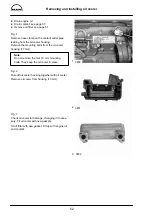
Removing and installing oil pump
55
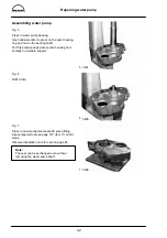
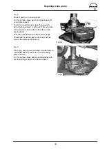
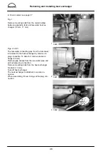
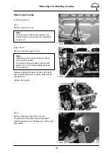
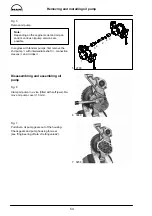
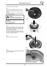
Fig. 8
Remove oil pump drive gear. To do this, lay pump
on suitable support and press off drive gear using
a mandrel.
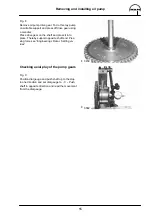
Place drive gear on the shaft and press it into
place. Thereby support opposite shaft end. Pres-
sing force see ”Engineering
S
Data
S
Setting va-
lues”.
Checking axial play of the pump gears
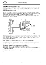
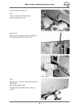
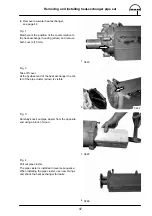
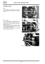
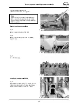
Fig. 9
Position dial gauge and push shaft up to the stop
in one direction and set dial gauge to - 0 -. Push
shaft in opposite direction and read the movement
from the dial gauge.
3459
3582
Summary of Contents for D 2866 LE 401
Page 1: ......
Page 17: ...Engine views D 2866 LE401 16...
Page 18: ...Engine views D 2866 LE401 17...
Page 19: ...Cross section of engine 18...
Page 20: ...Longitudinal section 19...
Page 124: ...123 Special tools...
Page 125: ...Special tools 124 2 3 4 5 6 7 9 1 8 6 1 6 2 6 3...
Page 129: ...Special tools 128 21 22 23 25 25 2 24 25 1 26 27 1 27 2 27 20 1 19 2 19 1 20 2 19 20...
Page 131: ...Special tools 130 29 28 30...
Page 138: ......


