4
5
6
7
Reworking valve seat
97
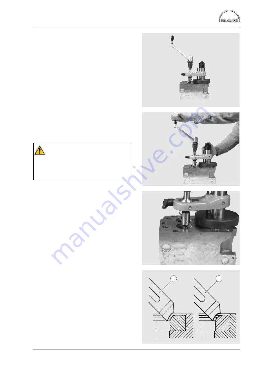
Fig. 4
Release the Jaccard lever, set the magnetic flange
down flat on the clamping plate and adjust the
height so that the forming cutter does not contact
the valve seat.
Set the toggle switch to position 1.
Tighten the Jaccard lever.
Fig. 5
Machine the valve seat by turning the driving crank
steadily in a clockwise direction and simulta-
neously operating the feed nut.
Caution:
During the machining process, turn the
crank vigourously and steadily but under
no circumstances against the direction of
turning as this may cause the carbide
cutting edge to break off.
Fig. 6
Once the valve seat has been cleanly machined,
reduce the working pressure of the forming cutter
by 2
−
3 turns without feed motion.
During these turns, turn the feed nut back
2
−
3 turns.
Press the toggle switch briefly to position 2 to lift
the magnetic field.
Now move the entire Mira tool upwards and insert
it in the next valve guide, repeating the centring
operation.
Use the same cutter settings for all the intake and
exhaust valve seats.
Fig. 7
Observe the specified seat angle.
À
Exhaust
Á
Intake
1
2
Summary of Contents for D 2842 LE 620
Page 1: ......
Page 2: ......
Page 20: ...Engine views D 2842 LE 620 18 7 1 2 4 3 5 6 7 1 2 4 11 9 10 8...
Page 136: ...134...
Page 137: ...135 Service Data...
Page 163: ...161 Special tools...
Page 164: ...Special tools 162 1 2 3 4 5 6 7 8 9 10 11 11 1 11 2 12 12 1 12 2 13 14...
Page 166: ...Special tools 164 15 1 15 2 15 3 15 4 15 5 1 2 7 15 6 3 4 5 6 15 7...
Page 170: ...Special tools 168 3 1 4 29 5 6 2 29 30 31 32 33 34 35...
Page 172: ...Special tools 170 36 37 38 39 42 40 41 44 2 44 1 44 43 1 43 2 43 3 43 45 46...
Page 178: ...176...
Page 179: ......
Page 180: ......


