9
10
11
Removing and installing crankshaft
120
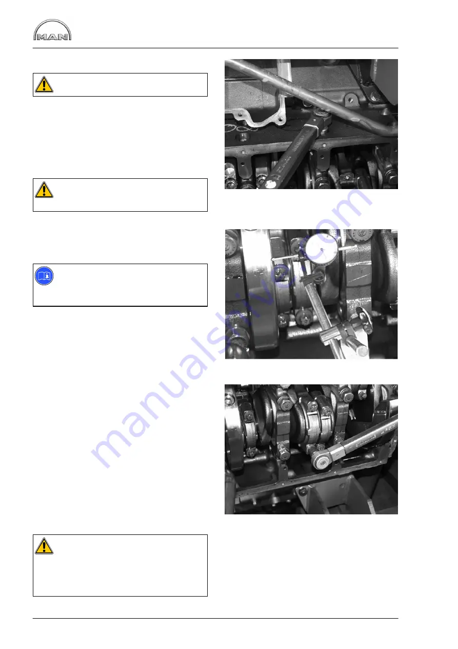
Fig. 9
Caution:
Removed bolts must be replaced.
Screw in the crankshaft bearing cover bolts and
tighten them.
Pretightening: 80
−
90 Nm
1st angle tightening: 90
_
2nd angle tightening: 90
_
Check that the crankshaft runs smoothly.
Caution:
Damaged bearing caps cannot be replaced
on an individual basis.
Checking axial clearance
Fig. 10
Note:
The axial clearance of the crankshaft is
determined by the crankshaft bearing
(alignment bearing) on the flywheel side.
D
Fit the dial gauge holder with dial gauge to the
crankcase
D
Apply the tip of the dial gauge to the crankshaft
D
Move the crankshaft back and forth in axial
direction and read off the clearance from the
dial gauge
D
If the permitted axial clearance is exceeded,
replace the main bearing shells completely
Fig. 11
Measure the conrod bearings, insert the pistons
with conrods. Coat the conrod bearing shells with
oil and pull the conrods to the journals.
Fit the conrod bearing covers with bearing shells
(observe marking
−
numbers must be on the same
side).
Screw in the mounting bolts and tighten them in
stages.
Pretightening: 100
−
110 Nm
Angle tightening: 90
_
Caution:
Removed bolts must be replaced.
After inadvertent attachment of cracked
conrods and conrod bearing covers that do
not belong together, the parts must not be
reused.
Fit oil pan and other detachable components.
Summary of Contents for D 2840 LE 301
Page 1: ......
Page 2: ......
Page 16: ...Notes 14...
Page 20: ...Engine views 18 Engine views D 2842 LE 301 9 10 11 12 9 8 6 5 4 3 2 1 13 14 15 16 17 18 6 7 8...
Page 150: ...Notes 148...
Page 151: ...149 Service Data...
Page 179: ...177 Special tools...
Page 180: ...Special tools 178 2 3 4 5 6 7 8 1 6 1 6 2 6 3 9 1 9 2 9 3 9...
Page 184: ...Special tools 182 21 22 25 25 2 24 25 1 26 27 1 27 2 27 20 1 19 2 19 1 20 2 19 20 28 23...
Page 186: ...Special tools 184 30 29 32 31 33...
Page 193: ......
Page 194: ......


