


PARTICLE SIZE
MASTERSIZER
3000
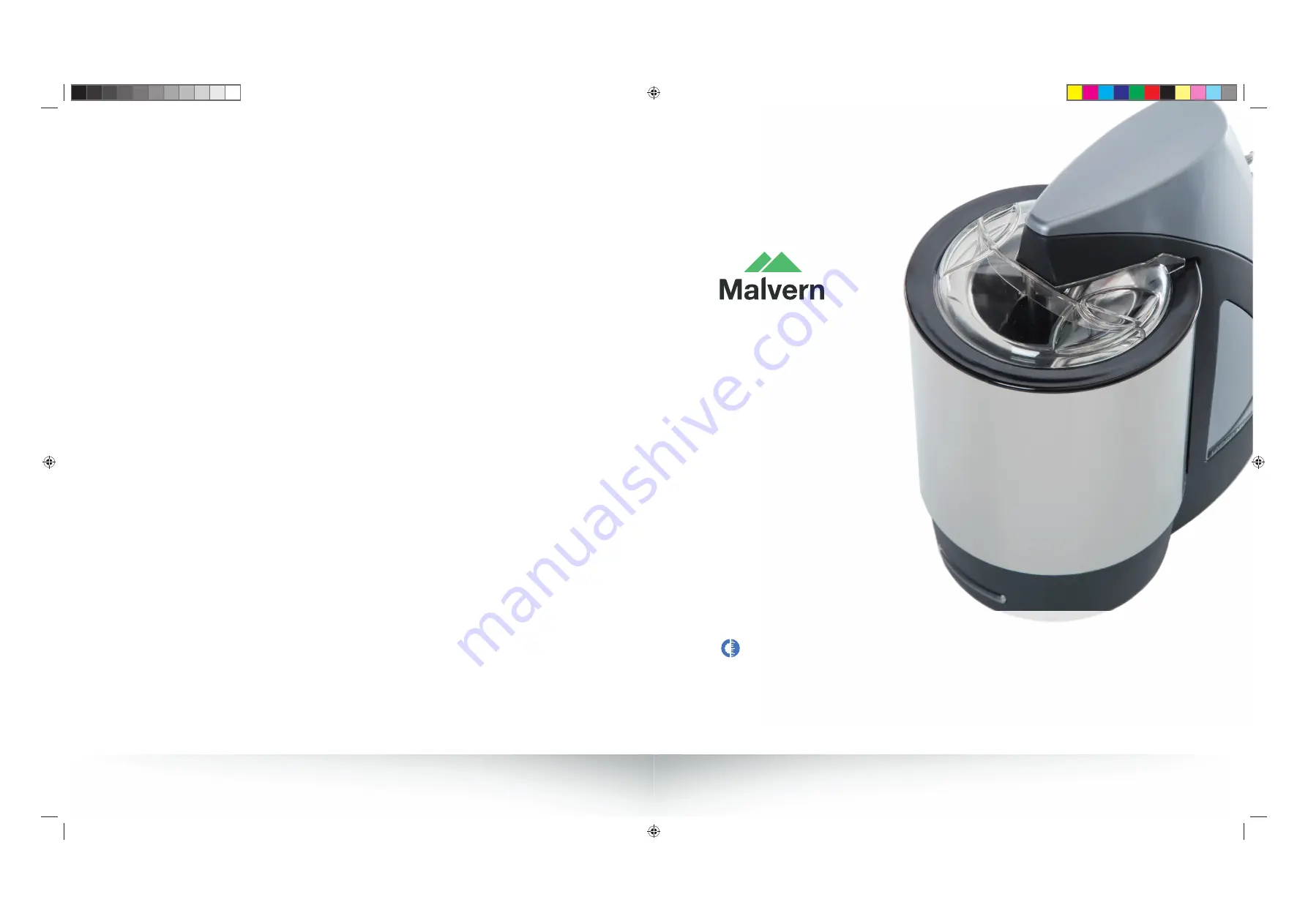
HYDRO SERIES
WET DISPERSION UNITS
MAN0479
MRK1955-01
www.malvern.com
Malvern Instruments Limited
Grovewood Road, Malvern
Worcestershire, WR14 1XZ, UK
Tel
+44 1684 892456
Fax
+44 1684 892789
MRK1955-01_HYDRO_dry_disp_units_cover_86pp.indd 1
MRK1955-01_HYDRO_dry_disp_units_cover_86pp.indd 1
28/08/2013 12:49:10
28/08/2013 12:49:10
Summary of Contents for HYDRO Series
Page 2: ......
Page 3: ...HYDRO SERIES WET DISPERSION UNITS MAN0479 06 EN 00...
Page 70: ......
Page 106: ......