INSTRUCTION MANUAL
MANUEL D'INSTRUCTION
MANUAL DE INSTRUCCIONES
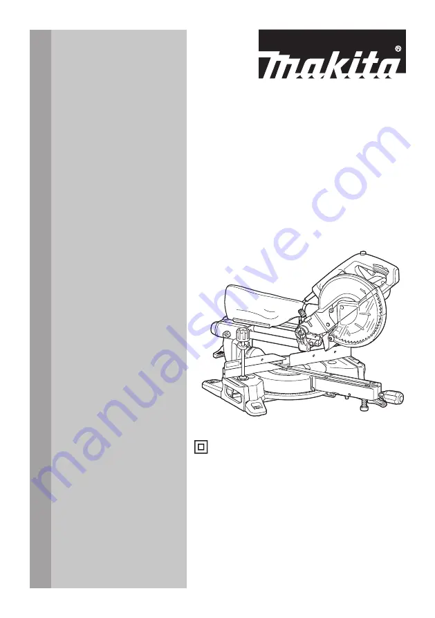
Slide Compound Miter Saw
Scie à Onglet Radiale
Sierra de Inglete Telescópica
LS0816F
IMPORTANT:
Read Before Using.
IMPORTANT :
Lire avant usage.
IMPORTANTE:
Lea antes de usar.
DOUBLE INSULATION
DOUBLE ISOLATION
DOBLE AISLAMIENTO


