background image

I N S T R U C T I O N   M A N U A L

WARNING:

For your personal safety, READ and UNDERSTAND before using.
SAVE THESE INSTRUCTIONS FOR FUTURE REFERENCE.

w w w . m a k i t a t o o l s . c o m
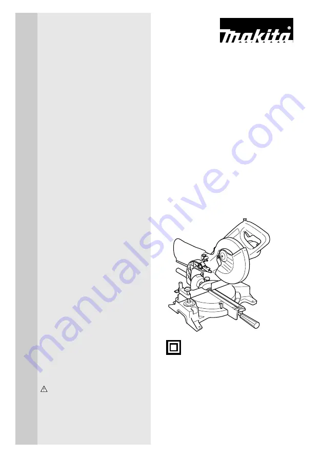
Slide Compound Saw

Equipped with Electric Blade Brake
190 mm (7-1/2”)
MODEL LS0711Z

DOUBLE
INSULATION

Summary of Contents for LS0711Z

Page 1: ...ING For your personal safety READ and UNDERSTAND before using SAVE THESE INSTRUCTIONS FOR FUTURE REFERENCE w w w m a k i t a t o o l s c o m Slide Compound Saw Equipped with Electric Blade Brake 190 mm 7 1 2 MODEL LS0711Z DOUBLE INSULATION ...

Page 2: ...0 mm x 458 mm 21 5 8 x 17 x 18 Net weight 10 5 kg 23 2 lbs Manufacturer reserves the right to change specifications without notice Specifications may differ from country to country For Your Own Safety Read Instruction Manual Before Operating Tool Save it for future reference GENERAL SAFETY PRECAUTIONS USA007 1 For All Tools Miter angle Bevel angle 0 45 left 0 60 mm x 150 mm 2 3 8 x 5 7 8 Note 1 50...

Page 3: ... 12 SECURE WORK Use clamps or a vise to hold work when practical It s safer than using your hand and it frees both hands to operate tool 13 DON T OVERREACH Keep proper footing and balance at all times 14 MAINTAIN TOOLS WITH CARE Keep tools sharp and clean for best and safest perfor mance Follow instructions for lubricating and changing accessories 15 DISCONNECT TOOLS before servicing when changing...

Page 4: ...ill cause a drop in line voltage resulting in loss of power and overheating Table 1 shows the correct size to use depending on cord length and nameplate ampere rating If in doubt use the next heavier gage The smaller the gage num ber the heavier the cord ADDITIONAL SAFETY RULES USB036 2 DO NOT let comfort or familiarity with product gained from repeated use replace strict adherence to slide compou...

Page 5: ...ed for this tool 15 Be careful not to damage the arbor flanges especially the installing surface or bolt Damage to these parts could result in blade breakage 16 Make sure that the turn base is properly secured so it will not move during opera tion Use the holes in the base to fasten the saw to a stable work platform or bench NEVER use tool where operator positioning would be awkward 17 For your sa...

Page 6: ...ct it from the receptacle Keep cord away from heat oil water and sharp objects 31 NEVER stack workpieces on the table top to speed cutting operations Cut only one piece at a time 32 Some material contains chemicals which may be toxic Take caution to prevent dust inhalation and skin contact Follow mate rial supplier safety data SAVE THESE INSTRUCTIONS WARNING MISUSE or failure to follow the safety ...

Page 7: ... the tool Blade guard When lowering the handle the blade guard rises automati cally The guard is spring loaded so it returns to its original position when the cut is completed and the handle is raised NEVER DEFEAT OR REMOVE THE BLADE GUARD OR THE SPRING WHICH ATTACHES TO THE GUARD In the interest of your personal safety always maintain the blade guard in good condition Any irregular operation of t...

Page 8: ... cut The kerf boards are factory adjusted so that the saw blade does not contact the kerf boards Before use adjust the kerf boards as follows First unplug the tool Loosen all the screws 2 each on left and right securing the kerf boards Re tighten them only to the extent that the kerf boards can still be easily moved by hand Lower the handle fully and push in the stopper pin to lock the handle in t...

Page 9: ...te the blade by hand while hold ing the handle all the way down to be sure that the blade does not contact any part of the lower base Re adjust slightly if necessary CAUTION After installing a new blade always be sure that the blade does not contact any part of the lower base when the handle is lowered completely Always do this with the tool unplugged Stopper arm The lower limit position of the bl...

Page 10: ...ngle on the bevel scale Then tighten the lever clockwise firmly to secure the arm CAUTION When tilting the saw blade be sure to raise the handle fully After changing the bevel angle always secure the arm by tightening the lever clockwise When changing bevel angles be sure to position the kerf boards appropriately as explained in the Positioning kerf boards section Switch action CAUTION Before plug...

Page 11: ...vents the tool from unintended starting NEVER use the tool if it runs when you simply pull the switch trigger without pressing the lock off button Return tool to a Makita service center for proper repairs BEFORE further usage NEVER tape down or defeat purpose and function of lock off button Electric brake This tool is equipped with an electric blade brake If the tool consistently fails to quickly ...

Page 12: ...e Makita socket wrench provided to install or remove the blade Failure to do so may result in overtightening or insufficient tightening of the hex bolt This could cause an injury Lock the handle in the raised position by pushing in the stop per pin To remove the blade use the socket wrench to loosen the hex bolt holding the center cover by turning it counterclock wise Raise the blade guard and cen...

Page 13: ... hex bolt left handed securely counter clockwise while pressing the shaft lock Return the blade guard and center cover to its original posi tion Then tighten the hex bolt clockwise to secure the center cover Release the handle from the raised position by pulling the stopper pin Lower the handle to make sure that the blade guard moves properly Make sure shaft lock has released spindle before making...

Page 14: ...iece WARNING It is extremely important to always secure the workpiece properly and tightly with the vise Failure to do so can cause the tool to be damaged and or the workpiece to be destroyed PERSONAL INJURY MAY ALSO RESULT Also after a cutting operation DO NOT raise the blade until the blade has come to a complete stop CAUTION When cutting long workpieces use supports that are as high as the top ...

Page 15: ...erations Horizontal vise optional accessory The horizontal vise can be installed on the left side of the base By turning the vise knob counterclockwise the screw is released and the vise shaft can be moved rapidly in and out By turning the vise knob clockwise the screw remains secured To grip the workpiece turn the vise knob gently clockwise until the projection reaches its topmost position then f...

Page 16: ...pin Make sure the blade is not contacting the workpiece etc before the switch is turned on Do not apply excessive pressure on the handle when cutting Too much force may result in overload of the motor and or decreased cutting efficiency Push down handle with only as much force as is necessary for smooth cutting and without significant decrease in blade speed Gently press down the handle to perform...

Page 17: ... may result 2 Slide push cutting cutting wide workpieces Loosen the clamp screw on the turn base counterclock wise so that the carriage can slide freely Secure the workpiece with the vise Pull the carriage toward you fully Switch on the tool without the blade making any contact and wait until the blade attains full speed Press down the handle and PUSH THE CARRIAGE TOWARD THE GUIDE FENCE AND THROUG...

Page 18: ...T THE WORKPIECE When the cut is completed switch off the tool and WAIT UNTIL THE BLADE HAS COME TO A COMPLETE STOP before returning the blade to its fully elevated position CAUTION Always be sure that the blade will move down to bevel direction during a bevel cut Keep hands out of path of saw blade During a bevel cut it may create a condition whereby the piece cut off will come to rest against the...

Page 19: ... length at the back of the work piece is the same as wall length Adjust cut length for angle of cut Always use several pieces for test cuts to check the saw angles When cutting crown and cove moldings set the bevel angle and miter angle as indicated in the table A and position the moldings on the top surface of the saw base as indicated in the table B Miter angle Left and Right 45 Right 50 Right 5...

Page 20: ... guide fence on the saw The finished piece to be used will always be on the LEFT side of the blade after the cut has been made For inside corner For outside corner Molding position in Fig A 1 2 3 4 Molding edge against guide fence Ceiling contact edge should be against guide fence Wall contact edge should be against guide fence Ceiling contact edge should be against guide fence Finished piece Fini...

Page 21: ... 8 1 74 39 0 39 2 115 25 0 21 4 155 9 8 7 8 75 38 7 38 7 116 24 7 21 0 156 9 4 7 5 76 38 4 38 2 117 24 3 20 7 157 9 0 7 1 77 38 1 37 7 118 23 9 20 3 158 8 6 6 8 78 37 8 37 2 119 23 6 19 9 159 8 3 6 5 79 37 4 36 8 120 23 2 19 6 160 7 9 6 2 80 37 1 36 3 121 22 8 19 2 161 7 5 5 9 81 36 8 35 8 122 22 5 18 8 162 7 1 5 6 82 36 5 35 3 123 22 1 18 5 163 6 7 5 3 83 36 2 34 8 124 21 7 18 1 164 6 3 4 9 84 35...

Page 22: ...9 3 74 34 4 43 2 115 22 3 24 3 155 8 8 8 9 75 34 1 42 7 116 22 0 23 8 156 8 5 8 5 76 33 9 42 1 117 21 7 23 4 157 8 1 8 2 77 33 6 41 6 118 21 4 23 0 158 7 8 7 8 78 33 3 41 1 119 21 0 22 6 159 7 4 7 5 79 33 1 40 6 120 20 7 22 2 160 7 1 7 1 80 32 8 40 1 121 20 4 21 8 161 6 7 6 7 81 32 5 39 6 122 20 0 21 4 162 6 4 6 4 82 32 3 39 1 123 19 7 21 0 163 6 0 6 0 83 32 0 38 6 124 19 4 20 6 164 5 6 5 7 84 31 ...

Page 23: ...er free cuts in workpieces Attach a wood facing to the guide fence using the holes in the guide fence See the figure concerning the dimensions for a sug gested wood facing CAUTION Use straight wood of even thickness as the wood facing Use screws to attach the wood facing to the guide fence The screws should be installed so that the screw heads are below the surface of the wood facing When the wood...

Page 24: ... the lower limit position of the blade using the adjusting screw and the stopper arm to limit the cutting depth of the blade Refer to Stopper arm section described on previously After adjusting the lower limit position of the blade cut parallel grooves across the width of the workpiece using a slide push cut as shown in the figure Then remove the workpiece material between the grooves with a chise...

Page 25: ...tool is not aligned properly perform the following 1 Miter angle Push the carriage toward the guide fence and tighten the clamp screw on the turn base to secure the carriage Loosen the grip which secures the turn base Turn the turn base so that the pointer points to 0 on the miter scale Then turn the turn base slightly clockwise and counterclockwise to seat the turn base in the 0 miter notch Leave...

Page 26: ...lever at the rear of the tool Turn the 0 bevel angle adjusting bolt lower bolt on the right side of the arm two or three revolutions counterclockwise to tilt the blade to the right Carefully square the side of the blade with the top surface of the turn base using the triangular rule try square etc by turning the 0 bevel angle adjust ing bolt clockwise Then tighten the lever securely 1 Screw 2 Mite...

Page 27: ...ve and check the carbon brushes regularly Replace when they wear down to the limit mark Keep the carbon brushes clean and free to slip in the holders Both carbon brushes should be replaced at the same time Use only iden tical carbon brushes Use a screwdriver to remove the brush holder caps Take out the worn carbon brushes insert the new ones and secure the brush holder caps After replacing brushes...

Page 28: ...orized or Factory Service Centers always using Makita replacement parts ACCESSORIES CAUTION These accessories or attachments are recommended for use with your Makita tool specified in this manual The use of any other accessories or attachments might present a risk of injury to persons Only use accessory or attachment for its stated purpose If you need any assistance for more details regarding thes...

Page 29: ...29 First Class Postage Required Post Office will not deliver without proper postage Makita U S A Inc 14930 Northam Street La Mirada CA 90638 5753 Fold Cut ...

Page 30: ...ability Power Other Design Features Size Price Makita Brand 5 Any comments MAIL THIS PORTION Your answers to the following questions are appreciated BE SURE TO COMPLETE THE CUSTOMER S PORTION OF THIS FORM AND RETAIN FOR YOUR RECORDS DATE PURCHASED MODEL NO SERIAL NO INTL LAST NAME COMPANY NAME STREET ADRESS CITY STATE AGE ZIP CODE PHONE AREA CODE STATUS Married SEX M F Single MONTH DAY YEAR Under ...

Page 31: ... St Louis MO 63126 2221 314 909 9889 NEBRASKA 4129 S 84th St Omaha NE 68127 402 597 2925 NEVADA 3375 S Decatur Blvd Suites 22 24 Las Vegas NV 89102 702 368 4277 NEW JERSEY 251 Herrod Blvd Dayton NJ 08810 1539 609 655 1212 NEW YORK 4917 Genessee Street Cheektowaga NY 14225 716 685 9503 OREGON 828 19th Avenue N W Portland OR 97209 503 222 1823 PENNSYLVANIA 1704 Babcock Blvd Pittsburgh PA 15209 412 8...

Page 32: ...one of Makita s Factory or Authorized Service Centers If inspection shows the trouble is caused by defective workmanship or material Makita will repair or at our option replace without charge This Warranty does not apply where repairs have been made or attempted by others repairs are required because of normal wear and tear the tool has been abused misused or improperly maintained alterations have...

Reviews: