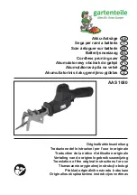
background image

PRODUCT

P 1/ 12

JR100D (RJ01

*1

)/ JR102D

10.8V Cordless Recipro Saw
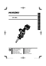
Dimensions: mm (")

Width (W)
Height (H)

Length (L)

355 (14)

63 (2-1/2)

146 (5-3/4)

Model JR100D (RJ01

*1

)/ JR102D are compact and lightweight

10.8V cordless recipro saws; JR100D (RJ01

*1

) is equipped with Toolless blade clamp

while JR102D is equipped with Blade clamp for both Recipro saw and Jig saw blades.

Their advantages are:

• Toolless blade clamp for Recipro saw blade (model JR100D [RJ01

*1

] only)

• Blade clamp compatible with both Recipro saw and Jig saw blades (model JR102D only)

• Compact and lightweight handy body for comfortable operation

• Multi-position switch enables various grip position for versatile operations.

Note: 

The standard equipment for the tool shown above may vary by country.

JR100D (RJ01

*1

)

[All countries]

These products are available in the following variations.

JR100DZ
JR100DWE

RJ01Z

RJ01ZW

DC10WA

DC10WA

DC10WB

Model No.

type

quantity Charger

2

2

2

BL1013

(Li-ion 1.3Ah)

BL1013

(Li-ion 1.3Ah)

BL1014

(Li-ion 1.3Ah)

Battery

Makita-blue
Makita-blue

white

RJ01

RJ01W

JR102DZ

Makita-blue

white

JR102DWE

Makita-blue

Housing

color

Yes

Yes

Yes

Plastic

carrying case

Offered to

All countries except North and

Central American countries

(Mexico & Guam are included.)

All countries except North and

Central American countries

(Mexico & Guam are included.)

North and Central

American countries

except Mexico and Guam

1.3

50 (2)

0 - 3,300

13 (1/2)

50 (2)

Li-ion

Pipe: Ø

Battery

Capacity: mm (")

Cell
Voltage: V

Capacity: Ah

14

Energy capacity: Wh

Strokes per minutes: min.

ˉ

¹= spm (strokes per minute)

Length of stroke: mm (")

Yes

Yes

Yes

No

1.2 (2.6)

1.1 (2.5)

LED job light 

Yes

Electric brake

Lock-off

Switch lock

Blade clamp type

Jig saw blade compatibility

Variable speed control by trigger

Weight according to EPTA-Procedure 01/2003: kg (lbs)

Wood

50 with DC10WA, (DC10WB

*

2

)

Charging time (approx.): min.

No

No

No

No

No

No

No

No

No

No

Yes

Hex

wrench

No

No

*1:

 Model number for North and Central American countries except Mexico and Guam

*2: 

for North and Central American countries except Mexico and Guam

10.8

,

 (10.8/12Vmax

*

2

)

Charger DC10WA (DC10WB for North and Central American countries except Mexico and Guam)

Battery BL1013 (BL1014 for North and Central American countries except Mexico and Guam)

Recipro saw blades, Jig saw blades (for JR102D only) 

Model No.

JR100D

 (

RJ01*

1

)

Toolless

Hex wrench is required.

JR102D

H

W

L

(Drawn above is

 Model JR100D.)

Model No.

 Description

C

ONCEPT AND MAIN APPLICATIONS


S

pecification

S

tandard equipment

O

ptional accessories

T

ECHNICAL INFORMATION

*1

: Model number for North and Central American countries

      except Mexico and Guam

All models also include the accessories listed below in "Standard equipment".

Recipro saw blade 100mm (for wood) .... 1

Recipro saw blade 100mm (for metal) .... 1

JR102D

[All countries except Sweden, Finland, Estonia]

Recipro saw blade 100mm (for wood) ....... 1

Recipro saw blade 100mm (for metal) ....... 1

Hex wrench 3 .............................................. 1

JR102D

[Sweden, Finland, Estonia]

Jig saw blade B-10 (for wood) .... 1

Jig saw blade B-18 (for wood) .... 1

Jig saw blade B-24 (for metal) .... 1

Hex wrench 3 ............................... 1

Summary of Contents for JR100DWE

Page 1: ... ion Pipe Ø Battery Capacity mm Cell Voltage V Capacity Ah 14 Energy capacity Wh Strokes per minutes min ˉ spm strokes per minute Length of stroke mm Yes Yes Yes No 1 2 2 6 1 1 2 5 LED job light Yes Electric brake Lock off Switch lock Blade clamp type Jig saw blade compatibility Variable speed control by trigger Weight according to EPTA Procedure 01 2003 kg lbs Wood 50 with DC10WA DC10WB 2 Chargin...

Page 2: ... Gear housing when removing 6902ZZ 1R281 Round Bar for Arbor 7 50 removing Ball bearing 6902ZZ from Gear housing 2 LUBRICATION Fig 1 Item No Description Shoulder pin 5 Whole surface of Pin for smooth twisting of Driving sleeve To the portion where Slider guide and Collared sleeve contacts To the teeth portion To the Pin portion Blade guide Slider guide Guide sleeve Driving sleeve Amount 5 g Portio...

Page 3: ...oe from Gear housing by unscrewing M4x10 Countersunk head screws from the both side of Gear housing Shoe Model JR102D Model JR102D Model JR100D Model JR100D Shoe Gear housing Gear housing 5a Remove Clamper Pin 3 and M6x10 Hex socket set screw So Blade clamp is removed from Slider 5 Remove M3x12 Hex socket head bolts 2pcs Now Blade holder section is removed from Slider Clamper Blade clamp M3x12 Hex...

Page 4: ... to the Loop side pass Slider guide through Slider 2 Pass Sponge seal through Slider Sponge seal protruded side of Slider guide Loop side Slider Slider 3 When assembling Slider to Gear housing cover face its projection side to the thin rib side of Gear housing cover 5 Fix Plate to Gear housing cover with M4x14 Pan head screws 4 Fitting the projection of Slider guide and Sponge seal to the Grooves ...

Page 5: ...o its small hole for Pin 3 is aligned to the same on Slider automatically 9a Pass Pin 3 through Blade clamp and Slider 10a Assemble Clamper to Blade clamp Do not approach from the Cut portion side of Blade clamp when assembling Concave Slider Fig 8 6 Set the following parts to the nearest point to the DC Motor side as illustrated below Collared sleeve 4 on Gear complete Loop portion of Slider 7 As...

Page 6: ...ove Gear complete with Arbor press Fig 10 or Fig 10A Fig 10 Fig 10A 1R258 1R281 Push 1R281 by applying it on the shaft of Gear complete with Arbor press Gear complete Ball bearing 6902ZZ If only Gear housing is removed and Ball bearing 6902ZZ remains in Gear housing remove the Ball bearing from Gear housing as drawn in Fig 11 1R258 1R258 1R281 1R258 Gear complete 1R258 1R258 Fig 11 1R132 1 Set 1R1...

Page 7: ...long tail into the slit of Blade guide And insert the short tail of the Torsion spring into the hole of Connecting sleeve Connecting sleeve Push pin 2 Insert Compression spring 2 and Push pin into the slit of Blade guide long tail short tail Compression spring 2 Connecting sleeve Blade guide Fig 12 1 Remove Protector and Retaining ring 16 by levering it up with Slotted screwdriver 3 Remove Guide s...

Page 8: ...g Shoulder pin 5 assemble Driving sleeve Note Locate this gray portion to Shoulder pin 5 and mount Driving sleeve to Guide sleeve Note These concaves on Connecting sleeve fit to the inner projection of Driving sleeve Driving sleeve Inner projection Fig 15 5 Press down Push pin with Slotted screwdriver till it stops while pushing Shoulder pin 5 6 And then remove Slotted Screwdriver So Push pin is p...

Page 9: ...h Water pump pliers over a cloth so as not to damage it Turn Driving sleeve 90 degrees while pressing it down Now Protrusions in the Driving sleeve presisely match to Depressions on Connecting sleeve and groove for Retaining ring 16 on Guide sleeve comes into your sight as drawn in Fig 18 Connecting sleeve Driving sleeve Fig 18 9 Mount the Retaining ring 16 as drawn below Groove for Retaining ring...

Page 10: ...lever F complete and Switch lever R Or remove Pin 3 before disassembling Switch lever F complete Pin 3 1 Remove Switch lever unit Switch lever F complete and Switch lever R 2 Remove Link and Switch lever R from Switch F complete Link Switch lever R Switch lever F complete 1 Mount Link to Switch lever F complete facing its triangle formed side to Switch lever R 2 Mount Switch lever R to the triangl...

Page 11: ... DC Motor and Gear housing Fix the Lead wires in these Lead wire holders Do not put Lead wires on this Rib Connector Store the extra portion of Lead wires in this space designated with gray color Rib B Boss B Rib A Tab Boss A Put the Lead wires between Boss B and Rib B Fix the Lead wires in these Lead wire holders Put the Lead wires between Rib A s Tab and the wall of Housing L and pass them betwe...

Page 12: ... wires white black from connector to this place and store them in this place DC Motor Fig D 3 Fig D 4 Wiring to DC Motor Wiring to Terminal Assemble DC Motor to Housing L the Lead wires must be faced to Housing R side the Lead wire black must be located to the Switch trigger side Connect the Lead wires to Terminal as drawn below Red point mark Housing L side Housing R side Bend the Terminal with b...

Reviews: