INSTRUCTION MANUAL
MANUAL DE INSTRUCCIONES
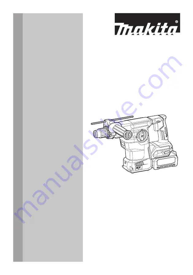
Cordless Combination Hammer
Martillo Rotativo Combinado
Inalámbrico
GRH08
GRH09
IMPORTANT:
Read Before Using.
IMPORTANTE:
Lea antes de usar.
Page 1: ...INSTRUCTION MANUAL MANUAL DE INSTRUCCIONES Cordless Combination Hammer Martillo Rotativo Combinado Inalámbrico GRH08 GRH09 IMPORTANT Read Before Using IMPORTANTE Lea antes de usar ...
Page 2: ... specifications herein are subject to change without notice Specifications may differ from country to country The weight may differ depending on the attachment s including the battery cartridge The lightest and heavi est combination according to EPTA Procedure 01 2014 are shown in the table Applicable battery cartridge and charger Battery cartridge BL4020 BL4025 BL4040 BL4050F BL4080F Recommended ...
Page 3: ...uipment such as dust mask non skid safety shoes hard hat or hearing protection used for appropriate conditions will reduce personal injuries 3 Prevent unintentional starting Ensure the switch is in the off position before connecting to power source and or battery pack picking up or carrying the tool Carrying power tools with your finger on the switch or energising power tools that have the switch ...
Page 4: ...zed service providers 3 Follow instruction for lubricating and chang ing accessories 4 Do not modify or attempt to repair the appli ance or the battery pack except as indicated in the instructions for use and care CORDLESS ROTARY HAMMER SAFETY WARNINGS 1 Wear ear protectors Exposure to noise can cause hearing loss 2 Use auxiliary handle s if supplied with the tool Loss of control can cause persona...
Page 5: ... contacts and pack up the battery in such a manner that it cannot move around in the packaging 11 When disposing the battery cartridge remove it from the tool and dispose of it in a safe place Follow your local regulations relating to disposal of battery 12 Use the batteries only with the products specified by Makita Installing the batteries to non compliant products may result in a fire exces siv...
Page 6: ...ting in the sun 22 Do not leave the wireless unit in a dusty or powdery place or in a place corrosive gas could be generated 23 Sudden change of the temperature may bedew the wireless unit Do not use the wireless unit until the dew is completely dried 24 When cleaning the wireless unit gently wipe with a dry soft cloth Do not use benzine thin ner conductive grease or the like 25 When storing the w...
Page 7: ... to become overloaded Then turn the tool on to restart Overheat protection When the tool or battery is overheated the tool stops automatically In this case let the tool and battery cool before turning the tool on again NOTE When the tool is overheated the lamp blinks Overdischarge protection When the battery capacity is not enough the tool stops automatically In this case remove the battery from t...
Page 8: ... to light up the lamp The lamp keeps on lighting while the switch trigger is being pulled The lamp goes out approximately 10 seconds after releasing the switch trigger CAUTION If the lamp goes off after blinking for a few seconds the active feedback sensing technology is not work ing properly Ask your local Makita Service Center for repair NOTE Use a dry cloth to wipe the dirt off the lens of the ...
Page 9: ...e line to the symbol Place the quick change drill chuck on the spindle of the tool Grasp the change cover of the quick change drill chuck and turn the change cover line to the symbol until a click can clearly be heard 1 4 2 3 Fig 8 1 Quick change drill chuck 2 Spindle 3 Change cover line 4 Change cover Selecting the action mode NOTICE Do not rotate the action mode chang ing knob when the tool is r...
Page 10: ... the dust collection system 1 Fig 12 1 Air duct Hook Optional accessory CAUTION Always remove the battery when hanging the tool with the hook CAUTION Never hook the tool at high loca tion or on potentially unstable surface The hook is convenient for temporarily hanging the tool Before installing the hook remove the rubber cap from the screw holes in the mounting bracket Insert the plate washers un...
Page 11: ...ge and proper function including fabric and stitching Do not use if damaged or not functioning properly 6 Do not wrap lanyards around or allow them to come in contact with sharp or rough edges 7 Fasten the other end of the lanyard outside the working area so that a falling tool is held securely 8 Attach the lanyard so that the tool will move away from the operator if it falls Dropped tools will sw...
Page 12: ...ration CAUTION After installing or adjusting the side grip make sure that the side grip is firmly secured with its retaining projections fully engaged by the position ing recesses on the gear housing To install the side grip follow the steps below 1 Loosen the thumb screw on the side grip Then install the side grip over the barrel neck of the gear housing 1 2 3 4 5 Fig 17 1 Side grip 2 Thumb screw...
Page 13: ...s and hold the lock button and then insert the depth gauge into the hex hole Make sure that the toothed side of the depth gauge faces the marking 1 2 3 4 Fig 23 1 Depth gauge 2 Lock button 3 Marking 4 Toothed side Adjust the depth gauge by moving it back and forth while pressing the lock button After the adjustment release the lock button to lock the depth gauge NOTE Make sure that the depth gauge...
Page 14: ...rel Then hold the attachment unit of the dust cup set and push it down onto the barrel to secure it in place 1 2 3 4 5 Fig 26 1 Dust cup set 2 Attachment unit 3 Spacer 4 symbol 5 Groove For model GRH09 Place the dust cup set onto the barrel neck of the gear housing aligning the symbol on the dust cup set with one of the grooves in the barrel Then hold the attachment unit of the dust cup set and pu...
Page 15: ...of the attachment unit Fig 33 DUST COLLECTION SYSTEM Optional accessory The dust collection system is designed to collect dusts effectively when the concrete drilling operation 1 Fig 34 1 Dust collection system CAUTION The dust collection system is intended for drilling in concrete only Do not use the dust collection system for drilling in metal or wood CAUTION When using the tool with the dust co...
Page 16: ...zle up to secure the dust collection system in place with a click so the air duct of the tool becomes covered with the suction air outlet of the dust collection system 1 3 2 4 5 6 Fig 35 1 Hooks 2 Dust collection system 3 Pockets 4 Nozzle 5 Air duct 6 Suction air outlet Uninstallation Press and hold the lock off button on the dust collection system and lower the nozzle to release the upper part of...
Page 17: ...t case three times after col lecting every 50 000 mm 3 of dust or when you feel the vacuum performance declined NOTE 50 000 mm 3 of dust equivalents to drilling 10 holes of ø10 mm and 65 mm depth 14 holes of ø3 8 and 2 depth 1 2 Fig 39 1 Dust case 2 Dial Disposing of dust CAUTION Always be sure that the tool is switched off and the battery cartridge is removed before carrying out any work on the t...
Page 18: ... tab slightly outwards and open the filter cover of the dust case 1 2 Fig 44 1 Filter cover 2 Lock tab 3 Remove the filter from the filter case 1 2 Fig 45 1 Filter 2 Filter case 4 Attach a new filter to the filter case and then attach the filter cover 5 Close the cover of the dust case and then attach the dust case to the dust collection system Replacing sealing cap A damaged or worn out sealing c...
Page 19: ...may result in the loss of control of the tool and potentially severe injury Set the action mode changing knob to the symbol Position the drill bit at the desired location for the hole then pull the switch trigger Do not force the tool Light pressure gives best results Keep the tool in position and prevent it from slipping away from the hole Do not apply more pressure when the hole becomes clogged ...
Page 20: ...g the quick change chuck for SDS plus Hold the ring and turn the sleeve counterclockwise to open the chuck jaws Place a drill bit in the chuck as far as it will go Hold the ring firmly and turn the sleeve clockwise to tighten the chuck 2 1 Fig 51 1 Sleeve 2 Ring To remove the drill bit hold the ring and turn the sleeve counterclockwise Diamond core drilling NOTICE If performing diamond core drilli...
Page 21: ...tion function Installing the wireless unit Optional accessory CAUTION Place the tool on a flat and stable surface when installing the wireless unit NOTICE Clean the dust and dirt on the tool before installing the wireless unit Dust or dirt may cause malfunction if it comes into the slot of the wireless unit NOTICE To prevent the malfunction caused by static touch a static discharging material such...
Page 22: ...registration NOTE During the tool registration do not pull the switch trigger or turn on the power switch on the vacuum cleaner NOTE Refer to the instruction manual of the vacuum cleaner too If you wish to activate the vacuum cleaner along with the switch operation of the tool finish the tool registra tion beforehand 1 Install the batteries to the vacuum cleaner and the tool 2 Set the stand by swi...
Page 23: ...tch on the vacuum cleaner to AUTO 1 Fig 61 1 Stand by switch 4 Push the wireless activation button on the tool briefly The wireless activation lamp will blink in blue 1 2 Fig 62 1 Wireless activation button 2 Wireless activation lamp 5 Turn on the tool Check if the vacuum cleaner runs while the tool is operating To stop the wireless activation of the vacuum cleaner push the wireless activation but...
Page 24: ...vacuum cleaner is available and the tool is running Tool registration Green 20 seconds Ready for the tool registration Waiting for the registration by the vacuum cleaner 2 seconds The tool registration has been finished The wireless activation lamp will start blinking in blue Cancelling tool registration Red 20 seconds Ready for the cancellation of the tool registration Waiting for the cancellatio...
Page 25: ...nd then become red After that press the wireless activation button on the tool in the same way 1 2 1 2 Fig 65 1 Wireless activation button 2 Wireless activation lamp If the cancellation is performed successfully the wire less activation lamps will light up in red for 2 seconds and start blinking in blue NOTE The wireless activation lamps finish blinking in red after 20 seconds elapsed Press the wi...
Page 26: ...ary according to the circumstances Before finishing the tool registration cancellation the switch of the tool is turned on or the power button on the vacuum cleaner is turned on Push the wireless activation button briefly and perform the tool registration cancellation procedures again The tool registration procedures for the tool or vacuum cleaner have not finished Perform the tool registration pr...
Page 27: ...use of any other accessories or attachments might present a risk of injury to persons Only use accessory or attachment for its stated purpose If you need any assistance for more details regard ing these accessories ask your local Makita Service Center Carbide tipped drill bits SDS Plus carbide tipped bits Core bit Bull point Diamond core bit Cold chisel Scaling chisel Grooving chisel Drill chuck s...
Page 28: ...luidas están sujetas a cambio sin previo aviso Las especificaciones pueden variar de país a país El peso puede variar en función de los accesorios incluido el cartucho de batería En la tabla se muestra la combinación de peso más ligero y más pesado conforme al procedimiento 01 2014 de EPTA Cartucho de batería y cargador aplicables Cartucho de batería BL4020 BL4025 BL4040 BL4050F BL4080F Batería re...
Page 29: ...able de extensión apro piado para uso en exteriores La utilización de un cable apropiado para uso en exteriores redu cirá el riesgo de que se produzca una descarga eléctrica 6 Si no es posible evitar usar una herramienta eléctrica en condiciones húmedas utilice un alimentador protegido con interruptor de cir cuito de falla a tierra ICFT El uso de un ICFT reduce el riesgo de descarga eléctrica 7 La...
Page 30: ...arse una situación peligrosa 8 Mantenga los mangos y superficies de asi miento secos limpios y libres de aceite o grasa Los mangos y superficies de asimiento resbalosos no permiten una manipulación segura ni el control de la herramienta en situaciones inesperadas 9 Cuando vaya a utilizar esta herramienta evite usar guantes de trabajo de tela ya que éstos podrían atorarse Si los guantes de trabajo ...
Page 31: ... y causarle una lesión grave a alguien 13 No toque la punta las partes cerca de la punta o la pieza de trabajo inmediatamente después de la operación éstas podrían estar extrema damente calientes y provocarle quemaduras en la piel 14 Algunos materiales contienen sustancias químicas que pueden ser tóxicas Evite inhalar polvo y que éste entre en contacto con la piel Consulte la hoja de seguridad de ...
Page 32: ...o suficientemente caliente como para provocarle quemaduras 16 No permita que las rebabas el polvo o la tierra que den atrapados en los terminales orificios y ranuras del cartucho de batería Podría provocar calenta miento incendio explosión y mal funcionamiento de la herramienta o del cartucho de batería lo que resultaría en quemaduras o lesiones personales 17 No utilice el cartucho de batería cerc...
Page 33: ...ministrado o en un contenedor libre de electricidad estática 26 No inserte ningún otro dispositivo que no sea la unidad inalámbrica de Makita en la ranura de la herramienta 27 No utilice la herramienta si la tapa de la ranura está dañada La entrada de agua polvo o sucie dad en la ranura podría causar una avería 28 No jale ni tuerza la tapa de la ranura más de lo necesario Vuelva a colocar la tapa ...
Page 34: ...erramienta y detenga la aplicación que causó que la herramienta se sobrecargara Luego encienda la herramienta para reiniciarla Protección contra sobrecalentamiento Cuando la herramienta o la batería se sobrecalienten la herramienta se detendrá automáticamente En este caso permita que la herramienta y la batería se enfríen antes de volver a encender la herramienta NOTA Cuando la herramienta se sobr...
Page 35: ...l motor se sobrecargará provocando que la herramienta se averíe AVISO El selector de ajuste gira entre la confi guración de número 1 y 5 Evite girar el selector hacia atrás y hacia adelante más ya que podría dañar la herramienta Iluminación de la luz delantera 1 Fig 5 1 Luz PRECAUCIÓN No mire a la luz ni vea a la fuente de luz directamente Jale el gatillo interruptor para encender la luz La luz co...
Page 36: ...io se desplace del símbolo al símbolo Tire del portabro cas de cambio rápido para SDS plus con fuerza si es necesario en la dirección de la flecha 1 2 3 Fig 7 1 Portabrocas de cambio rápido para SDS plus 2 Cubierta de cambio 3 Línea de la cubierta de cambio Instalación del portabrocas adaptador de cambio rápido Verifique que la línea del portabrocas adaptador de cambio rápido muestre el símbolo Su...
Page 37: ...s sobre cómo instalar el sistema de recolección de polvo consulte las instrucciones sobre la instalación del sistema de recolección de polvo 1 Fig 12 1 Conducto de aire Gancho Accesorio opcional PRECAUCIÓN Extraiga siempre la batería cuando vaya a colgar la herramienta con el gancho PRECAUCIÓN Nunca enganche la herramienta en un lugar elevado o en una superficie potencialmente inestable El gancho ...
Page 38: ...o de rosca Advertencias de seguridad sobre la conexión del cordel de seguridad correa de amarre al gancho Advertencias de seguridad específicas para uso en alturas Lea todas las advertencias de seguridad e instruc ciones El no seguir las advertencias e instrucciones podría ocasionar lesiones graves 1 Mantenga siempre la herramienta atada cuando trabaje en alturas La longitud máxima del cordel es d...
Page 39: ...sen ganchará del eje de salida Cuando esto suceda la broca dejará de girar Funcionamiento electrónico La herramienta está equipada con funciones electróni cas para facilitar la operación Freno eléctrico Esta herramienta está equipada con un freno eléc trico Si de manera consistente la herramienta no cesa de funcionar rápidamente después de soltar el gatillo interruptor lleve la herramienta a un ce...
Page 40: ...e la espiga de la broca dentro del portabrocas e insértelo lo más adentro del portabrocas mientras gira la broca con la mano para que el extremo de la espiga encaje bien en la hendidura del portabro cas y se acopla por completo Una vez instalada la broca trate de jalarla para asegu rarse de que está firmemente en su sitio 1 2 Fig 20 1 Broca 2 Portabrocas Para extraer la broca empuje hasta abajo la...
Page 41: ...ccesorio opcional Utilice el contenedor de polvo para evitar que el polvo caiga sobre la herramienta y sobre usted al realizar operaciones de perforación por encima de su cabeza Fije el contenedor de polvo en la punta tal como se muestra en la ilustración El tamaño de las puntas en las que el contenedor de polvo puede fijarse es el que se indica a continuación Modelo Diámetro de la punta Contenedo...
Page 42: ...el juego contenedor de polvo con una de las ranuras del depósito A continuación sujete la uni dad de fijación del juego contenedor de polvo y empú jela hacia abajo sobre el depósito para asegurarla en su sitio 1 2 3 4 Fig 27 1 Juego contenedor de polvo 2 Unidad de fijación 3 símbolo 4 Ranura NOTA Si conecta una aspiradora al juego contene dor de polvo retire la tapa guardapolvos antes de conectarl...
Page 43: ... únicamente No utilice el sistema de recolección de polvo para perforar en metal ni en madera PRECAUCIÓN Cuando vaya a utilizar la herramienta con el sistema de recolección de polvo asegúrese de colocar el filtro en el sistema de recolección de polvo para evitar la inhalación de polvo PRECAUCIÓN Antes de utilizar el sistema de recolección de polvo verifique que el filtro no esté dañado El no hacer...
Page 44: ...istema de recolección de polvo 3 Bolsillos 4 Boquilla 5 Conducto de aire 6 Salida de aire de succión Desinstalación Mantenga presionado el botón de desbloqueo del sis tema de recolección de polvo y baje la boquilla para liberar la parte superior del sistema de recolección de polvo Desenganche la parte inferior del sistema de recolección de polvo de la herramienta 1 2 3 Fig 36 1 Sistema de recolecc...
Page 45: ...e acumulen 50 000 mm3 de polvo o cuando crea que el rendimiento de aspiración se ha reducido NOTA 50 000 mm 3 de polvo equivalen a perforar 10 orificios de ø10 mm y 65 mm de profundidad 14 orificios de ø3 8 y 2 de profundidad 1 2 Fig 39 1 Caja para polvo 2 Selector Eliminación del polvo PRECAUCIÓN Asegúrese siempre de que la herramienta esté apagada y el cartucho de batería haya sido extraído ante...
Page 46: ...acia afuera y abra la cubierta del filtro de la caja para polvo 1 2 Fig 44 1 Cubierta del filtro 2 Pestaña de aseguramiento 3 Extraiga el filtro de la caja del filtro 1 2 Fig 45 1 Filtro 2 Caja del filtro 4 Coloque un filtro nuevo en la caja del filtro y luego fije la cubierta del filtro 5 Cierre la cubierta de la caja para polvo y luego fíjela en el sistema de recolección de polvo Reemplazo del t...
Page 47: ...g 48 Operación de taladrado con percusión PRECAUCIÓN En el momento de comenzar a penetrar cuando se obstruye el orificio con viru tas y partículas o cuando se topa contra varillas de refuerzo de concreto se ejerce una tremenda y repentina fuerza de torsión sobre la herramienta broca Utilice siempre la empuñadura lateral mango auxiliar y sujete firmemente la herra mienta tanto de la empuñadura late...
Page 48: ...SO Ejercer una presión excesiva sobre la herramienta no hará que consiga taladrar más rápido De hecho una presión excesiva sólo logrará dañar la punta de la broca de taladro reducir el des empeño y acortar la vida útil de la herramienta Ajuste la perilla de cambio de modo de accionamiento en el símbolo Para el modelo GRH08 Accesorio opcional Fije el adaptador de mandril en un portabrocas adapta do...
Page 49: ...partí culas de polvo de metal o material similar AVISO No instale ni extraiga el juego contene dor de polvo con la broca instalada en la herra mienta Esto podría dañar el juego contenedor de polvo y causar la filtración de polvo FUNCIÓN DE ACTIVACIÓN INALÁMBRICA Lo que puede hacer con la función de activación inalámbrica La función de activación inalámbrica permite una ope ración limpia y cómoda S...
Page 50: ... salientes con las partes cóncavas en la ranura 1 2 3 4 Fig 56 1 Unidad inalámbrica 2 Parte saliente 3 Tapa 4 Parte cóncava Cuando extraiga la unidad inalámbrica abra la tapa lentamente Los ganchos en la parte posterior de la tapa levantarán la unidad inalámbrica mientras usted jala hacia arriba la tapa 1 2 3 Fig 57 1 Unidad inalámbrica 2 Gancho 3 Tapa Una vez extraída la unidad inalámbrica guárde...
Page 51: ...terminarán parpadeando en verde después de un lapso de 20 segundos Oprima el botón de acti vación inalámbrica en la herramienta mientras la luz indicadora de activación inalámbrica en la aspiradora esté parpadeando Si la luz indicadora de activación inalámbrica no parpadea en verde oprima el botón de activación inalámbrica durante un lapso breve y vuelva a mantenerlo oprimido NOTA Cuando realice d...
Page 52: ...alrededores NOTA Cuando dos o más herramientas estén regis tradas en una aspiradora esta última podrá comen zar a funcionar incluso si usted no enciende su herra mienta debido a que otro usuario está utilizando la función de activación inalámbrica Descripción del estado de la luz indicadora de activación inalámbrica 1 Fig 63 1 Luz indicadora de activación inalámbrica La luz indicadora de activació...
Page 53: ...terruptor de modo en espera en la aspi radora en AUTO 1 Fig 64 1 Interruptor de modo en espera 3 Oprima el botón de activación inalámbrica en la aspiradora durante 6 segundos La luz indicadora de activación inalámbrica parpadeará en verde y luego se pondrá en rojo Después de eso oprima el botón de activación inalámbrica en la herramienta de la misma manera 1 2 1 2 Fig 65 1 Botón de activación inal...
Page 54: ...lada incorrectamente en la herramienta Instale la unidad inalámbrica correctamente La terminal de la unidad inalámbrica y o la ranura está sucia Retire con cuidado el polvo y la suciedad en la terminal de la unidad inalámbrica y limpie la ranura El interruptor de modo en espera en la aspiradora no está ajustado en AUTO Ajuste el interruptor de modo en espera en la aspiradora en AUTO No hay suminis...
Page 55: ...ales como dispositivos Wi Fi y hornos de microondas La aspiradora funciona mien tras la herramienta no está en funcionamiento Otros usuarios están usando la activa ción inalámbrica de la aspiradora con sus herramientas Apague el botón de activación inalámbrica de las demás herramientas o cancele el registro de dichas herramientas MANTENIMIENTO PRECAUCIÓN Asegúrese siempre de que la herramienta est...
Page 56: ...ntía no aplica para México Consulte la hoja de la garantía anexa para ver los términos más vigentes de la garantía aplicable a este producto En caso de no disponer de esta hoja de garantía anexa consulte los detalles sobre la garantía descritos en el sitio web de su país respectivo indicado a continuación Estados Unidos de América www makitatools com Canadá www makita ca Otros países www makita co...
Page 57: ...57 ...
Page 58: ...58 ...
Page 59: ...59 ...
Page 60: ...ados por el lijado aserrado esmerilado taladrado y otras actividades de la construcción contienen sustancias químicas reconocidas por el Estado de California como causantes de cáncer defectos de nacimiento y otros peligros de reproducción Algunos ejemplos de estos productos químicos son plomo de pinturas a base de plomo sílice cristalino de ladrillos y cemento y otros productos de albañilería y ar...