Makita DVC860L Technical Information Download Page 1

C

ONCEPT AND MAIN APPLICATIONS

Model DVC860L is a corded and cordless vacuum cleaner powered by AC and 

two 18V Li-ion batteries in series.

Its main features are as follows:

• Cloth filter type; for both Wet & Dry vacuum cleaning

• Large on-off switch; also equipped with main power switch

• Variable suction power control by dial

• Dual battery fuel gauge

• Removable storage box

• Removable power supply cord


for better maneuverability

Note:

 Not compatible with 1.3Ah Li-ion battery BL1815.

S

pecification

Model

Specification

DVC860L

Power unit

AC/DC

Battery

Voltage: V

36 (18x2)

Capacity: Ah

1.5, 2.0, 3.0, 4.0, 5.0

Energy capacity: Wh

27x2, 36x2, 54x2, 72x2, 90x2

Cell

Li-ion

Charging time (approx): min

15, 24, 22, 36, 45 with DC18RD

15x2, 24x2, 22x2, 36x2, 45x2 with DC18RC

Wet/Dry type

Wet & Dry

Variable suction power control

Yes (by dial)

Continuous run time (approx.) on a single full 

battery charge: minute

30 - 65 with two batteries BL1850; BL1850B

Suction power: W

on DC power

70 - 25

on AC power

320

Max sealed suction: kPa

on DC power

9

on AC power

24

Max air flow: m

3

/ minute on DC power

2.1

on AC power

3.6

Tank capacity: L

Wet

6

Dry

8

Noise: dB

on DC power

64

on AC power

75

Protection from electric shock

Double insulation

Power supply cord: m (ft)

*

1

North American countries: 6.0 (19.7),

Other countries: 5.0 (16.4)

Weight according to

EPTA-Procedure 01/2003

*

2

: kg (lbs)

8.6 (19.0)

*

3

, 9.2 (20.3)

*

4

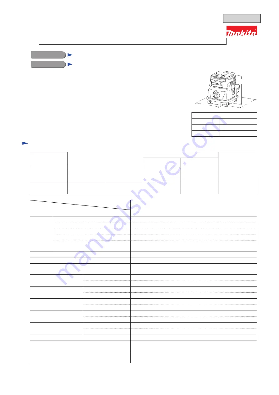
Dimensions: mm ( " )

Length (L)

366 (14-3/8)

Width (W)

334 (13-1/8)

Height (H)

368 (14-1/2)

*1 

As for the shord cord, connection cord is included.

*2 

With Plastic dust bag 650x650

*3 

With two batteries BL1815N; BL1820

*4 

With two batteries BL1830; BL1840, BL1840B; BL1850, BL1850B

Voltage (V)

Current (A)

Cycle (Hz)

Continuous Rating (W)

Max. Output (W)

Input

Output

110

10

50/60

1,050

---

---

120

9.2

50/60

---

---

---

220

5

50/60

1,050

---

---

230

4.8

50/60

1,050

---

---

240

4.6

50/60

1,050

---

---

OFFICIAL USE 

for ASC & Sales Shop

T

ECHNICAL INFORMATION

Model No.

Description

Corded and Cordless Vacuum Cleaner

DVC860L

L

W

H

PRODUCT


P 1/ 2

October 2015

Summary of Contents for DVC860L

Page 1: ...charge minute 30 65 with two batteries BL1850 BL1850B Suction power W on DC power 70 25 on AC power 320 Max sealed suction kPa on DC power 9 on AC power 24 Max air flow m3 minute on DC power 2 1 on AC...

Page 2: ...ry or model variation Hose complete 28 1 5 28 3 5 28 5 0 38 1 5 38 2 5 38 5 0 Front cuffs 22 24 38 Holder 10 33 Plastic dust bag set Powder filter Damper Pre filter Filter for wet vacuum cleaning Pape...

Page 3: ...lubricate BEARING EXTRACTOR removing Caster TYPE 72 FIELD INSERT JIG press fitting Caster ACRYLIC DUST BOX prevention against dust scattering RETAINING RING S AND R PLIERS removing Switch Apply Makita...

Page 4: ...ated with black arrow with Slotted head screwdriver Note No need to remove Grip 3 unless Grip 3 itself or Cowling 7 is replaced Slotted head screwdriver 3 Remove Switch button 4 by levering up with Sl...

Page 5: ...d wire holder 1 Tracing Lead wires connected to Motor assembly 39 disconnect the Connector that is connected to Controller C 65 2 Take out Motor assembly Fig 3 65 Connector 39 34 43 39 39 38 40 Small...

Page 6: ...ssembly Fig 4 a Fit the groove of Rubber ring 120 40 to the circumference rib c Put lead wires of Motor assembly to the notch of Brush holder 1 Assemble Rubber ring 120 40 to Motor assembly 39 while p...

Page 7: ...er ring 120 40 fits to the rib of Separator 34 at its groove portion 39 Rib 42 40 2 Pass the lead wires of Motor assembly 39 through the square hole for Lead wire passing Groove 42 40 5 Assemble Front...

Page 8: ...ute 3 Connect the lead wires of motor assembly 39 with those of Controller C 65 4 Set Top damper 9 to the reverse side of Cowling complete 7 aligning its notch to the center of Cowling complete 7 alig...

Page 9: ...out to the outside of Spacer 34 Screw boss Put lead wires of Power supply cord 36 so deep that they are not put on Screw boss Be careful not to put lead wires on Screw boss Terminal and Ribs for Term...

Page 10: ...mplete 7 closely touches Tank cover complete 43 when it is pushed 3 Tighten Cowling complete 7 with six 4x65 Tapping screws 6 4 Mount 2pcs of Compression spring 20 5 1 While pulling out Switch D2VW 01...

Page 11: ...EMBLY ASSEMBLY 1 Disassemble Motor assembly Fig 2 Fig 3 Disassemble Brush holder Fig 10 1 Inserting slotted head screwdriver to the illustrated portions alternately lift up Brush holder 69 Slit 69 67...

Page 12: ...ctly fitting to Groove 3 Set long arm of Brush spring to the groove of Carbon brush Long arm of Brush spring slipping off from the groove Conducting terminal Conducting terminal 4 Conducting terminal...

Page 13: ...way as Sub controller 16 5 Remove Stop ring E 7 17 and E 14 14 3 Remove Switch holder 11 together with Switch 13 from Switch base 18 3 2 Carbon brush set 3 3 Switch base section 3 DISASSEMBLY ASSEMBLY...

Page 14: ...ipe and Stopper 3 DISASSEMBLY ASSEMBLY 10 10 10 4x18 Tapping screw 2 pcs 11 Switch holder 13 Switch 14 Stop ring E 12 15 LED Circuit 16 Sub controller 17 Stop ring E 7 18 Switch base complete 19 O rin...

Page 15: ...rate Motor section together with Tank cover complete 43 and Float cage 48 from Tank 64 by releasing Hook 60 2 Unscrew three 4x18 Tapping screws 49 3 Separate Float cage 48 together with Float complete...

Page 16: ...complete 46 Inlet 62 61 1 Make a gap for 1R263 by applying Slotted head screwdriver to the joint of Caster 50 62 and Tank 64 2 Remove Caster 50 62 by levering it up with 1R263 inserted to the gap mad...

Page 17: ...mmer 1R274 61 62 Strike 1R274 applied to Casters 61 62 So Casters are assembled to Tank Triangle mark as a Notch 2 Assemble Bumper 51 tightly to Tank 64 Opposite side of Inlet Rear side Inlet side Fro...

Page 18: ...Y ASSEMBLY 1 Mount Holder 55 to Holder plate 54 2 Mount Holder 55 together with Holder plate 54 to Tank 64 4 Fasten Inlet 59 to Holder plate 54 through Holder 55 and Tank 64 with three 4x28 Tapping sc...

Page 19: ...th screws to right Tightening torque N m 1 5 1 8 3 pcs 2 pcs 1 pc 1 3 1 8 0 5 0 7 Screws used Qty Stopper Stopper Straight pipe Straight pipe 59 64 6 7 34 43 48 49 10 11 18 57 60 60 Hook 64 Tank 10 4x...

Page 20: ...187 with lock Switch Flag receptacle 187 with lock covered with insulated sleeve Switch D2VW 01 3HS 29 and Motor assembly 39 K Closed end connector 18 Switch base complete Sub controller Terminal A Te...

Page 21: ...Black Red 3a COM 1a 1b 3b 2b 2a NO AS AS 33 29 36 65 28 39 27 32 35 13 16 15 K CN CN CN CN CN K CN CN 18 AWG AWG American Wire Gauge 22 AWG 18 AWG 18 AWG 18 AWG 22 AWG 18 AWG 22 AWG 18 AWG 22 AWG 22 A...

Page 22: ...The gap between Non insulated terminal and Cord seal 56 has to be less than 3mm Earth line 120 Bottom view of Tank Tank Pass the lead wire through the groove of Holder plate 54 Fix the lead wire with...

Page 23: ...to Motor assembly that the lead wire can be guided out as shown Fig D 3 Do not put Lead wires connected to Motor assembly on Rubber ring Rubber ring Rib J Separator Motor Do not put Lead wires connect...

Page 24: ...s for connecting to Controller C to this Lead wire holder Boss B Pass Power supply cord through the route between Boss A Rib A Rib B Rib C Rib D and Boss B Pass the following Lead wires through the ro...

Page 25: ...n Relay Put Connector 10 poles and sag portion of its Lead wires to the place between Rib M and Rib N Do not put Connectors lead wires 4 poles on Relay Rib Q Fig D 6 Put the lead wires for connecting...

Page 26: ...ead wires on Heatsink Put the Closed end splices connected with main Switch to this area Put the following lead wires and connectors to this area Closed end splices connecting Controller A s lead wire...

Page 27: ...k white which are connected to Terminal block through Line filter And put Line filter inside of Rib I Pass the lead wires black white which are connected to Terminal block through Line filter And put...

Page 28: ...responding to switch operation when 10 times repeat of ON OFF action Go to No if the motor runs now and then Power lamp green is ON The machine does not have any trouble Speed can be changed with Dial...

Page 29: ...e broken Motor assembly is broken Other mechanical trouble Replace Controller B Replace Controller B Replace Controller C Replace Motor assembly Replace Main switch Replace Main switch Replace ON OFF...

Reviews: