2 / 11
R
epair
CAUTION: Repair the machine in accordance with “Instruction manual” or “Safety instructions”.
1 NECESSARY REPAIRING TOOLS
2 DISASSEMBLY/ASSEMBLY
Code No.
Description
Use for
1R402-A
-
-
-
Digital tester
checking Controller
No.1 Phillips screwdriver
press-fitting Ball bearing 6000DDW
No.2 Phillips screwdriver
press-fitting Ball bearing 6901DDW/6001DDW
Slotted bit 10
Slotted screwdriver
removing Ball bearing 6803ZZ
-
removing Carrier complete
Index
1 NECESSARY REPAIRING TOOLS
P 2
2-1. Removing Harness
P 2
2-2. Replacing Motor and Fan 94
P
2-7
2-3. Disassembling/Assembling of Upper Housing
P 8-12
2-4. Replacing/Cleaning of Rear Block Filter
P
13-14
Circuit Diagram
P 25
Wiring Diagram
P 26-30
3 TROUBLESHOOTING
P 31-33
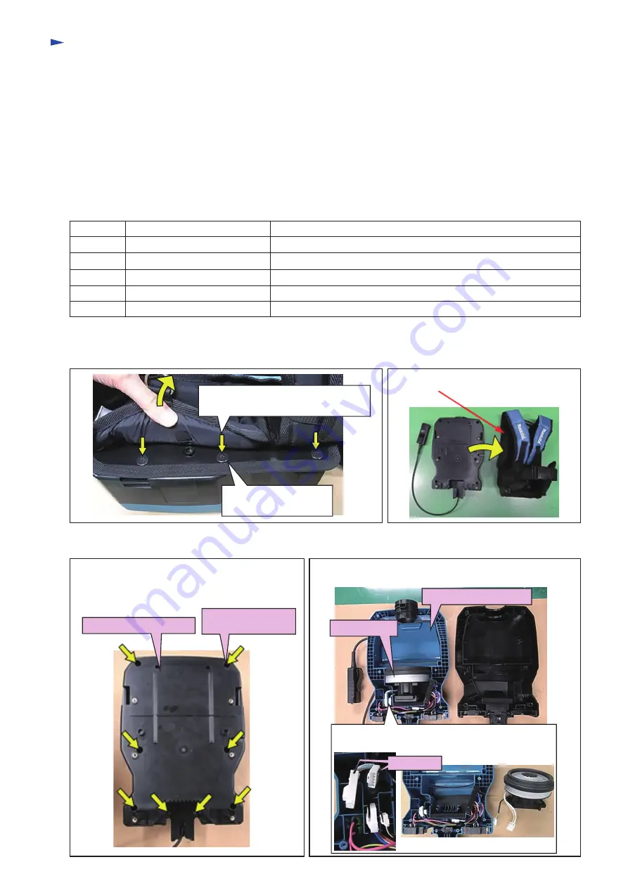
[2]-2. Replacing Motor and Fan 94
Fig. 2-2-1
Fig. 2-2-2
2-1. Removing Harness
Fig. 2-1-1
Fig. 2-1-2
(1) Pull up Back pad of Harness and
remove six M5 + Flat head screws.
The other three screws
are on the opposite side.
(2) Remove Harness.
(1) Remove Harness as shown in
[2]-1
.
(2) Remove Lower housing complete by unscrewing
eight 4x18 Tapping screws as shown below.
(3) Lift up and take Motor section out of Upper housing
complete.
Lower housing complete
4x18 Tapping screw
(8 pcs)
Motor section
Upper housing complete
(4) Separate Motor section from Upper housing
complete by disconnecting two Connectors.
Connectors

