background image

12 ENGLISH

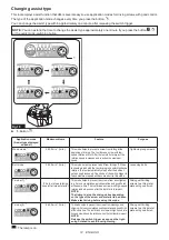
Changing assist type

This tool employs assist function that offers several easy-to-use application modes for driving screws with good control.
The type of the application mode changes every time you press the button 

.

You can change the assist type within approximately one minute after releasing the switch trigger.

NOTE:

 You can extend the time to change the assist type approximately one minute if you press the button 

or the quick mode-switching button.

1

Fig.10

►    

1.

 Button 

Application mode

(Assist type displayed 

on panel)

Maximum blows

Feature

Purpose

Wood mode *

3,800 min

-1

 (/min)

This mode helps to prevent a screw from falling at the 

beginning of driving. The tool drives a screw with low-

speed rotation at first. After the tool starts to impact, the 

rotation speed increases and reaches the maximum 

speed.

Tightening long screws. 

Bolt mode

3,800 min

-1

 (/min)

This mode helps to prevent a bolt from falling off. When 

loosening a bolt with the tool driving in counterclockwise 

rotation, the tool automatically stops after the bolt/nut 

gets enough loosened. The stroke of the switch trigger to 

reach maximum speed will become short in this mode.

Loosening bolts.

T mode (1) *

– 

(The tool stops rotating 

soon after impact starts.)

This mode helps to prevent the screws from over-tighten-

ing. It also accomplishes quick operation and good finish 

at the same time. The tool drives a screw with high-speed 

rotation and stops soon after the tool starts to impact.

NOTE:  

The timing to stop the driving varies depending 

on the type of the screw and material to be driven. 

Make a test driving before using this mode.

Driving self-drilling 

screws to a thin metal 

plate with good finish.

T mode (2) *

2,600 min

-1

 (/min)

This mode helps to prevent the screws from breakage and 

stripping. It also accomplishes quick operation and good finish 

at the same time. The tool drives a screw with high-speed rota-

tion and slows down the rotation when the tool starts to impact.

NOTE:  

Release the switch trigger as soon as the tight-

ening finished to avoid overtightening.

Driving self-drilling 

screws to a thick metal 

plate with good finish.

: The lamp is on.

Summary of Contents for DTD173

Page 1: ...INSTRUCTION MANUAL Cordless Impact Driver DTD173 ENGLISH Original instructions Read before use ...

Page 2: ...60B Charger DC18RC DC18RD DC18RE DC18SD DC18SE DC18SF DC18SH DC18WC Some of the battery cartridges and chargers listed above may not be available depending on your region of residence WARNING Only use the battery cartridges and chargers listed above Use of any other battery cartridges and chargers may cause injury and or fire Symbols The followings show the symbols which may be used for the equipm...

Page 3: ...uropean countries only The Declarations of conformity are included in Annex A to this instruction manual SAFETY WARNINGS General power tool safety warnings WARNING Read all safety warnings instructions illustrations and specifications provided with this power tool Failure to follow all instructions listed below may result in electric shock fire and or serious injury Save all warnings and instruc t...

Page 4: ...e power tool if the switch does not turn it on and off Any power tool that cannot be controlled with the switch is dangerous and must be repaired 3 Disconnect the plug from the power source and or remove the battery pack if detachable from the power tool before making any adjust ments changing accessories or storing power tools Such preventive safety measures reduce the risk of starting the power ...

Page 5: ... for the subject product MISUSE or failure to follow the safety rules stated in this instruction manual may cause serious personal injury Important safety instructions for battery cartridge 1 Before using battery cartridge read all instruc tions and cautionary markings on 1 battery charger 2 battery and 3 product using battery 2 Do not disassemble or tamper with the battery cartridge It may result...

Page 6: ...ervice life 3 Charge the battery cartridge with room tem perature at 10 C 40 C 50 F 104 F Let a hot battery cartridge cool down before charging it 4 When not using the battery cartridge remove it from the tool or the charger 5 Charge the battery cartridge if you do not use it for a long period more than six months FUNCTIONAL DESCRIPTION CAUTION Always be sure that the tool is switched off and the ...

Page 7: ...n operation 1 Turn the tool off and then turn it on again to restart 2 Charge the battery ies or replace it them with recharged battery ies 3 Let the tool and battery ies cool down If no improvement can be found by restoring protection system then contact your local Makita Service Center Indicating the remaining battery capacity Only for battery cartridges with the indicator Press the check button...

Page 8: ...n to the highest 1 2 Fig 6 1 Button 2 Switch panel NOTE You can hold the button continuously to cycle the brightness between the three levels and the light off state NOTE When the tool is overheated the front lamp flash for one minute and then the switch panel goes off In this case cool down the tool before operating again NOTE To confirm the lamp status pull the trigger when the reversing switch ...

Page 9: ...pplica tion mode to the tool 1 Fig 8 1 Quick mode switching button When the application mode is not registered The level of impact force changes every time you press the quick mode switching button The front lamp will flash once when the impact force is changed by press ing the quick mode switching button When the application mode is registered The tool switches between the registered application ...

Page 10: ...mode switching function is ON Switching to the registered application mode Press The front lamp on the tool flash once Registering the application mode Press and hold each button Example Wood mode is registered The lamp of desired application mode blinks Erasing the registered application mode Press and hold each button All impact force grade lamps blink Disabling resuming the quick mode switching...

Page 11: ...imum force and speed Driving screws to underwork materi als tightening long screws or bolts 3 Hard 3 600 min 1 min Tightening with less force and speed than Max mode easier to control than Max mode Driving screws to underwork materi als tightening bolts 2 Medium 2 600 min 1 min Tightening when a good finishing is needed Driving screws to finishing boards or plaster boards 1 Soft 1 100 min 1 min Ti...

Page 12: ...ving in counterclockwise rotation the tool automatically stops after the bolt nut gets enough loosened The stroke of the switch trigger to reach maximum speed will become short in this mode Loosening bolts T mode 1 The tool stops rotating soon after impact starts This mode helps to prevent the screws from over tighten ing It also accomplishes quick operation and good finish at the same time The to...

Page 13: ... force for quick mode switching function Once register it you can switch to the max impact force from T mode by just one click of the quick mode switching button Also you can return to T mode by pressing the quick mode switching button again Even if the tool is in other application mode than T mode pressing the quick mode switching button changes to max impact force It is convenient for you to reg...

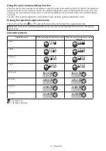
Page 14: ...lica tion mode The lamp of the registered application mode will blink when using the registered application mode Erasing the registered application mode Press and hold the button and button at the same time until all impact force grade lamps blink NOTE After erasing the registered application mode the quick mode switching button works for changing the impact force Indication patterns Application m...

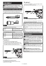
Page 15: ...re 2 In addition to Procedure 1 insert the bit piece into the sleeve with its pointed end facing in 1 3 2 Fig 14 1 Driver bit 2 Bit piece 3 Sleeve To remove the driver bit pull the sleeve in the direction of the arrow and pull the driver bit out NOTE If the driver bit is not inserted deep enough into the sleeve the sleeve will not return to its original position and the driver bit will not be secu...

Page 16: ...le result ing in injuries to you or people around or below you Use the hanging hole at the bottom rear of the tool to hang the tool on a wall using a hanging cord or similar strings 1 Fig 16 1 Hanging hole OPERATION The proper fastening torque may differ depending upon the kind or size of the screw bolt the material of the workpiece to be fastened etc The relation between fas tening torque and fas...

Page 17: ...rect size driver bit or socket bit will cause a reduction in the fastening torque 3 Bolt Even though the torque coefficient and the class of bolt are the same the proper fasten ing torque will differ according to the diame ter of bolt Even though the diameters of bolts are the same the proper fastening torque will differ according to the torque coefficient the class of bolt and the bolt length 4 T...

Page 18: ...18 ...

Page 19: ...19 ...

Page 20: ...www makita com Makita Europe N V Makita Corporation 3 11 8 Sumiyoshi cho Anjo Aichi 446 8502 Japan Jan Baptist Vinkstraat 2 3070 Kortenberg Belgium 885A16 226 EN 20221026 ...

Reviews: