background image

8

Adjusting    


the carburetor

NOTE: The grinding parts are equipped with an electronic 

ignition to limit the speed. 
At the factory the idling speed has been set to approx. 

2,500 1/min., but the running-in process of a new engine 

may require slight readjustment of the idling speed.

A

For correct adjustment of the idling speed the following 

steps must be carried out:

Start the engine and run it until it is warm

  (about    -  5  

minutes).

B

Adjust the carburetor with the screwdriver (

1

, Order No. 944 

40 00) included with the Power Cut. It has a lug that helps 

with adjustment.

Readjust the idling speed.

If the cut-off disc is still turning when the engine is running, 

unscrew the adjusting screw of the throttle valve (

2

) until the 

cut-off disc is no longer turning. When the engine is left running 

at idling speed, loosen the screw a little.

Switch off the engine.

1

2

C

2

1

Summary of Contents for DPC7311HD

Page 1: ...fety Manual Improper use can cause serious injury The engine exhaust from this product contains chemicals known to the State of California to cause cancer birth defects or other reproductive harm Preserve this Manual carefully Instruction and Safety Manual for Gasoline Power Cuts DPC7311HD DPC7321HD ...

Page 2: ...t part or malfunction of authorized parts due to use of non authorized parts OWNER S WARRANTY RESPONSIBILITIES As the engine owner you are responsible for the performance of the required maintenance listed in your owner s manual MAKITA recommends that you retain all receipts covering maintenance on your engine but MAKITA cannot deny warranty solely for the lack of receipts or for your failure to e...

Page 3: ... electronic ignition hermetically sealed to protect against dust and moisture Vibration damping with the MAKITA2 mass system D2M for tireless working even when guiding the Power Cut by hand Five stage air filter system for reliable working even under very dusty conditions Two options for mounting the cutter attachment Either cen trally for good balance when guiding the unit manually or on the side...

Page 4: ...s Particular care and caution Forbidden Wear helmet and eye respiratory and hearing protection Wear protective gloves Wear respiratory protection Hazardous dust and or gas emission Fire hazard from flying sparks No smoking No open fire Direction of cutting wheel rotation Warning the max peripheral speed of the cutting disc is 80 m s Cutting disc dimensions Never use carbide tipped circular saw bla...

Page 5: ...der the influence of alcohol drugs medica tion or other substances which may impair vision dexterity or judgement A fire extinguisher must be available in the immediate vicinity when working in easily inflammable vegetation or when it has not rained for a long time danger of fire Asbestos and other materials that can release toxins may be cut only with the necessary safety precautions and after no...

Page 6: ...ithin the extended swing range of the cutting disc direction of sparks Fuel cannot be stored for an unlimited period of time Buy only as much as will be consumed in the near future When making up the gasoline oil mixture always put the oil in the mixing container first and then the gasoline Use only approved and marked containers for the transport and storage of fuel Keep fuel away from children P...

Page 7: ...r Cut into operation only as described in this instruc tion manual 13 Always place your left foot in the rear handle and grasptheotherhandlefirmly withthumbandfingers Otherstarting methods are not allowed WhenstartingthePowerCutitmustbewellsupportedandsecurely held The cutting disc must not be touching anything If the cutting disc is new test it by running it at least 60 seconds at topspeed Whendo...

Page 8: ...er leave the Power Cut unattended Use the Power Cut at high speed as far as possible see Tech nical Data Only use the Power Cut during good light and visibility periods Be aware of slippery or wet areas and of ice and snow risk of slipping Never work on unstable surfaces Make sure that there are no obstacles in the working area risk of stumbling Always ensure that you have a safe footing Never cut...

Page 9: ... material Instead always cut shallow around the whole piece Worn discs have a smaller diameter than new discs so that at the same engine speed they have a lower effective circumfer ential speed and therefore do not cut as well Cut I beams and L bars in steps see Figure 21 Cut bands and plates like pipes along the wide side with a long cut Whencuttingmaterialunderstress supportedmaterialormate rial...

Page 10: ... move the unit with the engine on or the disc moving Carry the unit only by the tubular middle handle with the cut ting disc pointing behind you 26 Avoid touching the exhaust muffler burn hazard When moving the Power Cut over longer distances use a wheelbarrow or wagon When transporting the Power Cut in a vehicle make sure it is securely positioned in such a way that no fuel can leak out Always re...

Page 11: ...ccessories or cutting discs increases the risk of accident We cannot accept any respon sibility for accidents or damage occurring in association with the use of cutting discs or accessories other than original MAKITA First aid For the event of a possible accident please make sure that a firstaidkitisalwaysimmediatelyavailablecloseby Immediately replace any items used from the first aid box When ca...

Page 12: ...x torque Nm 5 0 Idling speed rpm 2 500 Clutch engagement speed rpm 3 800 Engine speed limitation rpm 9 350 Max spindle speed rpm 4 300 Sound pressure level at the operators ear 1 dB A 104 Sound pressure level at the bystander s position 50 ft 1 dB A 86 Vibration acceleration ah w per EN 1454 Tubular handle idle rated spindle speed m s2 7 6 Rear handle idle rated spindle speed m s2 8 7 Carburetor d...

Page 13: ...lace the cutting disc 5 on the arbour 7 NOTE The arbor hole of the cutting disc must be an exact fit with the arbor or shaft Make sure the cutting disc is installed so it turns in the right direction if a direction is marked on the disc For the the following work use the assembly tools included with delivery 1 13 19 AF combination wrench 2 Allen key 3 Carburetor adjustment screwdriver Place the Po...

Page 14: ...en the V belt after the first hour of operation Fuels Caution The Power Cut uses mineral oil products gasoline and oil Be especially careful when handling gasoline Do not smoke Do not allow gasoline to come near flames sparks or fire explosion hazard Fuel mixture The Power Cut is powered by a high performance two stroke engine It runs on a mixture of gasoline and two stroke engine oil The engine i...

Page 15: ...l tank filler neck to keep dirt from getting in the tank Place the unit on its side on an even surface Unscrew the tank cap and fill tank with fuel mixture Take care to avoid spilling Screw the tank cap back on hand tight After refuelling clean screw cap tank and check for lekages Never start or operate the Power Cut in the same place as it was fuelled If fuel gets on your clothing change clothes ...

Page 16: ... way that the cutting disc is not touching anything D 1 2 3 meters 10 feet Move the protective hood 3 into the proper position for the work you intend to do see illustration Grasp the grip 2 The hood 3 can swing in both ways within its range of motion Caution Alwaysmakesurethatthestraightouteredgeoftheimpactplate 4 and the edge of the hood are parallel see arrows If this is not the case take the t...

Page 17: ...t audible ignition Caution Do not pull out the starter cable more than approx 50 cm and lead it back by hand Depress decompression valve F 5 again Put the combination switch F 6 in position I Keep pulling the starter cable until the engine catches As soon as the engine is running press the throttle F 9 to release the half throttle lock F 7 allowing the engine to idle Warm starting As described und...

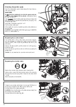
Page 18: ...ollowing steps must be carried out Start the engine and run it until it is warm about 3 5 minutes B Adjust the carburetor with the screwdriver 1 Order No 944 340 001 included with the Power Cut It has a lug that helps with adjustment Readjust the idling speed If the cut off disc is still turning when the engine is running unscrew the adjusting screw of the throttle valve 2 until the cut off disc i...

Page 19: ...ting wheel breaks during cutting the Power Cut must be repaired by a MAKITA service center before being used again SERVICE Unscrew the screws 8 and remove the crankcase housing cover 9 Remove the old belt 10 or belt pieces Clean out the inside of the drive arm with a brush Put in a new V belt NOTE Reassemble the crankcase housing cover 9 side piece C 6 and cover C 4 in the reverse order To tighten...

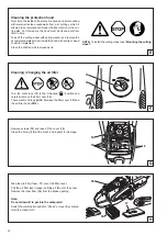
Page 20: ...o install the cutting wheel see Mounting the cutting wheel F Cleaning changing the air filter Turn the cover lock 11 to the Unlocked position and carefully remove the filter cover 12 There are two O rings G 15 between the filter cover 12 and the air filter hood G 14 G Remove screws 13 and take off the cover 14 Clean the O ring 15 with a brush and inspect for damage 13 14 15 H Take the pre filter f...

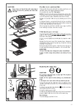
Page 21: ...eplacement pre filter on hand Replace the pre filter after every 20 operating hours at the latest To improve filtration wet the pre filter with air filter oil Before doing this carefully clean the pre filter with air filter cleaner Be sure to follow manufacturer s instructions When inserting the pre filter in the filter cover align it with the cover opening and press it into the cover 5 Filter ins...

Page 22: ...Remove starter housing 15 Unscrew two screws 16 and carefuly remove the air guide 17 from the starter housing 15 Proceed in the order A B C D Remove all pieces of cable 18 15 18 14 17 16 A B C D F G Thread in a new starter cable dia 4 0 mm length 1000 mm as shown don t forget the disc 19 and knot both ends Pull knot 20 into the cable pulley 21 CAUTION Do not let the knots or the cable ends protrud...

Page 23: ... on until you hear it catch Put the circlip back on Wind on the starter cable see above under Replacing the starter cable Reinstall the air guide see Fig A When putting the starter housing back on it may be necessary to pull the starter handle slightly until the starting mechanism engages Guide the cable into the recess 24 on the cable drum and use the cable to turn the drum two turns in the direc...

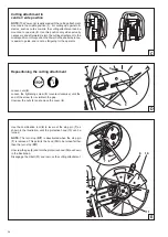
Page 24: ...as fatiguing for the operator 1 2 C Repositioning the cutting attachment Loosen nuts 5 Loosen the tightening screw 3 counter clockwise until the end of the screw 4 is visible in the gap Unscrew the nuts 5 and remove the cover 6 D Use the combination tool 8 to lever out the stop pin 7 as shown in the illustration until the protective hood 10 can be turned NOTE The turn stop D 7 is deactivated when ...

Page 25: ...4 F 19 20 Replacing cleaning the spark arrester screen The spark arrester screen should be checked and cleaned regularly Models without catalytic converter Loosen the 2 screws 19 and remove the spark arrester screen 20 Models with catalytic converter Unscrew and remove screws 21 Remove the front housing section of the muffler 22 Unscrew and remove screw 23 Remove the deflector plate and spark arre...

Page 26: ...off the trolley The water tank comes with all necessary connections and hoses Mounting to the trolley and Power Cut are very fast and simple Mains pressure water system 6 The mains pressure water system is designed to be mounted on the Power Cut It can be used with or without the trolley but is especially suitable for applications involving hand held stationarycutting Thewaterlinehasafast releasec...

Page 27: ...erly Failure to perform the prescribed maintenance work can lead to accidents Users of the Power Cut must not perform any maintenance work not described in this Instruction Manual All such work must be carried out by a MAKITA service center Page Service spare parts and guarantee Maintenance and repair The maintenance and repair of modern cutoff saws and their safety related components requires qua...

Page 28: ...uretor adjustment may be involved muffler clogged exhaust channel in cylinder simultaneously clogged spark arrester screen clogged Guarantee MAKITA guarantees the highest quality and will therefore reimburse all costs for repair by replacement of damaged parts resulting from material or production faults occurring within the guarantee period after purchase Please note that in some countries partic...

Page 29: ...r 5l fuel 2 5l oil Pos MAKITA No Qty Denomination Synthetic resin cutting disc 1 966 144 150 1 Cutting disc for steel dia 350 25 4 mm 14 1 0 1 966 144 120 1 Cutting disc for masonry dia 350 25 4 mm 14 1 0 3 994 280 250 1 Hex screw M8x25 4 965 300 470 1 V belt 5 963 601 120 1 Suction head 6 010 114 091 1 Tank cap compl fuel 8 394 173 020 1 Inner filter 9 394 173 010 1 Air filter insert paper cartri...

Page 30: ...30 ...

Page 31: ...31 ...

Page 32: ... Specifications subject to change without notice Form 995 704 755 11 07 GB To find your local distributor please visit www makita outdoor com Makita U S A Inc 14930 Northam Street La Mirada CA 90638 5753 ...

Reviews: