GB
16
29. DO NOT STO P COMPRESSOR BY PULLING OUT THE
PLUG
Use the “AUTO/OFF” knob of pressure switc h.
30. USE ONLY RECOMMENDED AIR HANDLING PARTS
ACCEPT ABLE FOR PRESSURE NOT L ESS TH AN 125 PSI
(8.6 B AR)
Risk of bursti ng. Use onl y recommended air handling parts
acceptabl e f or pressur es not less than 125 psi ( 8.6 bar).
REPLACEMENT PARTS
When s ervicing us e onl y identic al replac ement parts.Repairs
shoul d be conducted onl y by authorized s ervic e center.
SAFETY
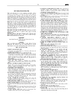
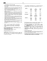
GROUNDING INSTRUCTIONS
This compress or shoul d be grounded while in us e to prot ect the
operator from elec tric shoc k.The compress or is equipped with a
three-conductor cord and three-prong grounding t ype pl ug to fit the
proper grounding type receptacle. The green (or green and yellow)
conductor in the cord is t he grounding wire. Never connect the
green (or green and yellow) wire to a li ve termi nal. If your units is
for use on less than 150 volts, it has a plug that looks like t hat
shown i n s ketch (A) i n figure on the right. An adapter, see s ketches
(B) and (C), is availabl e for connecti ng sketch (A) type pl ugs to
two- prong receptacles. T he green-color ed rigid ear, lug, or the like
extending from t he adapt er mus t be connected t o a permanent
ground, s uch as a properly grounded outlet box.
NOTE:
the
grounding adapt or, sketch (C), is prohibited in Canada by
Canadian El ectrical Code Part. 1. Theref ore, the instruc tions f or its
use are not applicable in Canada.
EXTENSION CORD
Use onl y three-ext ension cords t hat have three-prong grounding
type plugs and three-pole receptables t hat acc ept the compr essor’s
plug. Replac e or repair damaged c ord. Make sure your extension
cord is in good c ondition. When usi ng an extension cord, be sur e to
use one heavy enough to carr y the current your product will draw.
An undersized cord will caus e a drop in line volt age resulting in
loss of power and overheating. Table s hows the correct size to use
depending on c ord lenght and name plat e ampere rating. If in
doubt, use the next heavier gage. T he smaller the gage number,
the heavier the c ord.
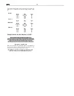
Tab.1 SECTION VALID FOR A MAX LENGHT OF 20 mt single-
phas e
HP kW
220/230V
50 Hz (mm²)
110/120V
60 Hz (mm²)
0.75 0.65 1.5 2.5
1 0.75 1.5 2.5
1.5 1.1 2.5 4
2 1.5 2.5
4
-6
3 2.2 4 /
W ARNING
Avoid electrical s hoc k haz ard. Never us e t his compress or wit h a
damaged or frayed electrical c ord or ext ensi on cor d. Ins pect all
electrical cords regularly. Never use i n near wat er or in any
environment where electric shoc k is possible
SAVE THIS INSTRUCTION AND MAKE THEM
AVAILABLE OTHER USERS OF THIS TOOL!
OPERAT ION AND MAINTEN ANCE NOTE:
The inf ormation
cont ained in this Instr uction Manual is designed to assist you in the
safe operation and maintenance of the compress or. Some
illustrations in this Instruc tion Manual may show details or
attac hments that differ from those on your own c ompressor.
INSTALL ATION
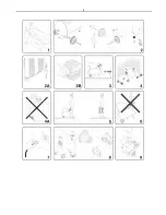
After havi ng removed t he compress or from its
pac king (fig. 1) and having chec ked its perfec t integrit y, making
sure that it has not been damaged during transport, proceed as
follows .
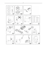
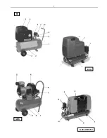
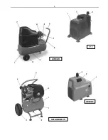
COMPRESSOR W ITH TANK (FIG.20)
Fit the wheels and the rubbers on the tanks where t hese have not
been fitt ed, f ollowi ng the instr uctions provided in fig. 2. Also fit the
air filter (fig. 2B) in c ompressors in which t his has not been fi tted.
COMPRESSOR W ITHOUT TANK (FIG.21)
Fit the suc tion cups underneat h t he base of the unit as indic ated in
fi g.2A. Position the compress or on a fl at s urface or one with an
inclination of 10° at the most (fig. 3), in a well-ventilated area away
from at mos pheric agents and not in explosi ve areas . If the surface
is sloping and smooth, make sure that the c ompressor does not
move while running, ot herwis e bloc k t he wheels with two wedges.
If t he s urfac e c onsists of a s helf or t he ledge of a stand, make sure
that it may not f all off by sec uring it appropriat ely. The compress or
must be positioned at l east 50 c m away from any walls to ensure
its ideal ventilation and eff ecti ve c ooling. (fig. 4).
THIS COMPRESSOR RUNS W ITHOUT OIL (4A)
OPERAT IONAL INSTRUCTIONS
-
Transport the compr essor in the correct manner wit hout tipping it or
lifting it with hooks or ropes . (fig. 5 - 6)
ELECTRICAL CONNECTION
The
single-phase compressors
are supplied c omplet e with an electrical c able and two-pol e + earth
power plug. The c ompressor must be connec ted t o a power s oc ket
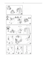
provided with eart h connection. (fig. 7)
W ARNING:
The eart h connec tion must be ac hieved acc ording to the industrial
safet y s tandar ds (EN 60204). The plug of t he power s upply c able
must not be used as a s witch but must be plugged into a power
socket t hat is controlled by a suitable differ ential s witc h (magneto
thermal s witch).
STARTING
Make sure that the mai ns voltage corresponds to t hat indicated on
the el ectrical dat a nameplat e (fig. 8), the admit ted tolerance range
must remain withi n ± 5%.
COMPRESSOR W ITH TANK (Fig. 20):
Turn or press, depending
on the t ype of press ure s witch fitt ed on t he equipment, the knob
situat ed in the upper part to «0» (fig. 9). Put t he pl ug in the power
socket (fi g. 7) and turn t he knob to «I». Attac h the rubber hos e or
the spiral t ype hose to t he appr opriat e fi tting situated near the
pressure s witch (fig.25). The c ompressor runs in a c omplet ely
aut omatic manner and is c ontrolled by the press ure s witch t hat
stops it when t he pressur e inside t he tank reac hes the maximum
pressure and s tarts it again when the press ure falls bac k down to
the minimum l evel. The diff erenc e in press ure is usually 2 bar (29
psi) roughly bet ween t he maximum and mi nimum value. I.e.: the
compressor st ops when it reac hes 8 bar (116 psi) ( max. running
pressure) and is aut omaticall y re-start ed when the press ure inside
the tank f alls t o 6 bar (87 psi). Aft er having connected the
compressor t o the el ectrical power suppl y line, l oad to the
maxi mum pressure and chec k t he c orrect efficienc y of the
mac hine.
COMPRESSOR W ITHOUT TANK (Fig. 21)
: Put t he plug in the
power soc ket (fig. 7). Press the starting push butt on situated at the
side of the compressor (fig. 9A). T his t ype of compress or is
provided wit h a devic e that automaticall y controls the maximum
wor king pressure even if t he us er is not using compressed air.The
compressor aut omaticall y r eleas es t he exc ess air from a val ve
situat ed on t he head. The c ompressor does not st op automatic ally.
Use the ON/OFF pus h butt on to s top the c ompressor. Att ach the
rubber hos e or the spiral t ype hos e t o the appropriate fi tting
situat ed at t he top of the c ompressor, near the gear mot or (fig. 25).
NOTE:
The head/c ylinder/ deli ver y hos e unit situated beneat h the
panelling may r each high temperat ures t heref ore be c areful when
wor king near these components and do not touch t hem to avoid
getting burned (fig. 10).
Summary of Contents for AC1300
Page 4: ...4 ...
Page 5: ...5 ...
Page 6: ...6 ...
Page 7: ...7 FX ECU GMS S ECU FB 210 ...
Page 8: ...8 F 1 AIRCLIK SERIE F S MAGNUM VS ...
Page 54: ...Cod 734 637 0000 02 2008 ...

