background image

15.2 Solar circuit

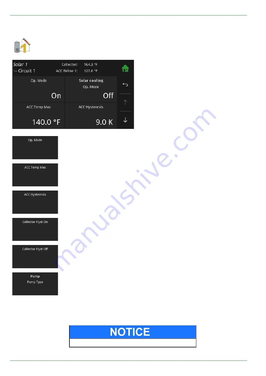
Solar circuit 1 and 2

are in menu Solar.

Solar circuit

has following menu items:

• Operation Mode

• ACC Temp Max

• ACC Hysteresis

• Collector Hyst On

• Collector Hyst Off

Off:
On:

No charge
Charge as long as

Collector tempe hysteresis

is lower than the

temperature of the

Adj ACC sensor below

or the

ACC temp max

If the temperature in the ACC is higher than the ACC temp Max, the solar pump
switches off. The limit sensor measures the temperature in the ACC.

The solar circuit pump is switched off due to the ACC temp Max is reached. The
temperature must fall under ACC temp Max minus hysteresis, then the solar cir-
cuit pump switches on again. The hysteresis prevents a solar pump cycling (On
Off On Off).

If the temperature differnce between the collector sensor and TPU, ACC lower
sensor is higher than the Coll Hyst A, the solar pump switches On.

If the temperature differnce between the collector sensor and TPU, ACC lower
sensor is lower than the Coll Hyst A, the solar pump switches Off.

The menu

Pumptype

contains the following modes:

Asynchronus:

Asynchronus pump – direct output 230VAC on/off

Async.Regulated:

Asynchronus pump – pulsed output 230VAC

Heating Efficient:

PWM1 - PWM signal inverted

Solar Efficient:

PWM2 - PWM direct signal

Note:

When using a A-class pump as

Accumulator pump

the pump cannot be re-

gulated from Solar circuit 2.

Material damage by false selection of pump!

PE 568 USA 2.0

48

Solar circuit

Summary of Contents for PES 20

Page 1: ...alling and servicing SAVE THESE INSTRUCTIONS Operating Manual Pellet heating with auger delivery or vacuum suction system for the end user AutoPellet PES 20 32 56 FA_V3 10 AutoPellet TOUCH USA PE 568...

Page 2: ...8 USA 2 0 Version valid from 09 2021 Approved Wohlinger Christian Author Manufacturer MAINE ENERGY SYSTEMS LLC 8 Airport Road P O Box 547 Bethel Maine 04217 E Mail info maineenergysystems com MAINE EN...

Page 3: ...on system 22 7 3 Auger delivery system 22 7 4 Storage systems 23 7 4 1 Pellet storage room 23 7 4 2 Flexilo fabric tank 23 8 Operating the Pellematic 24 8 1 Operating the heating system 24 8 2 Descrip...

Page 4: ...US 77 17 7 E Mail 78 17 8 IP Config 79 18 Software 84 19 Emptying the ash pan 85 20 Emptying the ash box 86 21 Maintenance and servicing 88 21 1 Maintenance 88 21 2 Cleaning the boiler every year 89 2...

Page 5: ...place for future reference Installation and first startup must be carried out by a qualified installer certified by Maine Energy Systems The installation must comply with the requirements of the Auth...

Page 6: ...ing systems and hot water supply for buildings It is not permissible to use the pellet boiler for any other purpose Reasonable foreseeable inadvertent uses for the pellet boiler are not known The boil...

Page 7: ...ead to death or life threatening injury Warning indicates a situation that could lead life threatening or serious injury Caution indicates a situation that could lead to injury Note indicates a situat...

Page 8: ...openings in the combustion air inlet must never be partially or completely closed Ventilation systems central vacuum cleaning systems extractor fans air conditioning systems flue gas blowers dryers fu...

Page 9: ...on R Ri is sk k o of f c cu ut t i in nj ju ur ri ie es s d du ue e t to o s sh ha ar rp p e ed dg ge es s Use gloves for performing all work on the boiler D Da am ma ag ge e t to o p pr ro op pe er r...

Page 10: ...t to do in the event of a fire Switch off the heating system Call your local fire department and or 911 Use approved fire extinguishers fire protection class ABC What to do if you smell smoke Switch o...

Page 11: ...R Ri is sk k o of f f fi ir re e Do not store flammable materials or liquids in the vici nity of the pellet boiler Do not permit unauthorized persons to enter the boiler room Keep children away Do no...

Page 12: ...and design of the chimney is very important The chimney must be able to ensure suffi cient draft to safely draw away the flue gas regardless of the status of the boiler Low flue gas tempera tures can...

Page 13: ...y and thus increases fuel consumption 3 Negative pressure of the chimney The boiler must be connected to a chimney or a vertical venting system that is capable of handling and producing a negative bre...

Page 14: ...create an extremely hot fire The chimney and the chimney connector should be inspected at least twice monthly during the heating season to determine if a creosote buildup has occurred If creosote has...

Page 15: ...system volume will dictate the required expansion tank size I In ni it ti ia al l s st ta ar rt t u up p The initial start up of each MESys boiler must be per formed by an authorized installer 5 5 Ins...

Page 16: ...matic is con nected to or with Pellet boiler Make and Model number ____________________ Existing boiler Make and Model number _____________________ P Po os ss si ib bl le e e es sc ca ap pe e o of f f...

Page 17: ...et ts s t th ha at t c co op pn nt ta ai in n t tr re ea at te ed d w wo oo od d c co ol lo or re ed d p pa ap pe er r p pr ro od du uc ct ts s c ca ar rd db bo oa ar rd d s so ol lv ve en nt ts s p...

Page 18: ...p pr ro od du uc ct ts s c ca ar rd db bo oa ar rd d s so ol lv ve en nt ts s p pl la as st ti ic c t tr ra as sh h o or r g ga ar rb ba ag ge e Never burn trash plastics gasoline solvents naphtha ho...

Page 19: ...m an ash box with ash compression system and an integrated return water temperature control The installed programmable logic controller system en ables fully automatic operation and highest efficiency...

Page 20: ...Key components of the Pellematic 1 Boiler heat exchanger 2 Vac Hopper Day tank 3 Burner 4 External automatic ash compression system 5 Boiler controller PE 568 USA 2 0 20 The pellet boiler...

Page 21: ...0 Burner fan 3 Heat exchanger 11 External ash box 4 Boiler water 12 Burner auger 5 Boiler insulation 13 Electronic ignition 6 Combustion chamber cover 14 De ashing system 7 Suction turbine 15 Ash cham...

Page 22: ...ge room 5 Suction flap Located underneath the fabric tank Pellet boiler Version A pellet storage room Version B fabric tank 7 3 Auger delivery system The auger system consists of Delivery system motor...

Page 23: ...traction system is part of the koFEN pellet heating system The sloping base is to be provided by the customer Information and important notes on setting up storage rooms can be found in the koFEN plan...

Page 24: ...in nc co or r r re ec ct t s se et tt ti in ng gs s Only trained operators may use the heating system Make sure no unauthorised persons enter the central heating room Keep children away from the cent...

Page 25: ...controller 2 Main switch Switches off the heating system both poles including the power supply to the control panel 3 Safety temperature sensor Switches the heating system off if the boiler temperatur...

Page 26: ...PE 568 USA 2 0 26 Setting language date and time at Pelletronic Touch...

Page 27: ...Setting language date and time at Pelletronic Touch 27 Setting the date Setting the time Operating Manual AutoPellet PES 20 32 56...

Page 28: ...y mode As soon as you touch the surface of the touch light turns on and displays the opening window 1 Measuring values adjustable 2 Date 3 Hour 4 The icon house takes to the main menu 5 Weather displa...

Page 29: ...ectly to the main menu The horizontal arrow leads you one step back With the blue down arrow you get to additional lines of information on this item Down scroll down With the blue up arrow you get to...

Page 30: ...enter values within the min max range 3 Time and date block a Adjustable time or date b Cancel c Help function inactive d Confirm 4 Text selection a Name of parameter b Status texts The number of stat...

Page 31: ...Main Menu 31 8 7 Main Menu In the Main menu you see all submenus By finger pressure on an icon you reach the respective submenu Operating Manual AutoPellet PES 20 32 56...

Page 32: ...Menu navigation of Pelletronic Touch PE 568 USA 2 0 32 Main Menu...

Page 33: ...f The adjusted operating mode of the heating circuits and DHW is inactive The frost protection function is active Auto The adjusted operating mode of the heating circuits and DHW is active The frost p...

Page 34: ...es is in the Main menu Pellematic Heating circuit Domestic hot water Solar Accumulator Return pump Heating Plant In the menu item Allocation you see which heating circuits are allocated to the boiler...

Page 35: ...arger nearby place Search with the following details Postal code location country Postal code country Location country Afterwards weather data for the next 3 days are downloaded An icon for the curren...

Page 36: ...Furnace starts in the heating times according to the Set room temperature Heating The Furnace heats constantly according to the Set room temperature Set back The Furnace heats constantly according to...

Page 37: ...ng values Actual value Set value Inputs sensores Outputs pumps mixer and motors Outside Temperature actual Outside Temperature Boiler Temp actual Boiler Temperature Booster Status Booster On Off Flow...

Page 38: ...s for these hea ting days Mo Th 8 With and you switch between the heating blocks You can deactivate heating days in the heating block and activate in another 4 The heating times for Mo Th are assig ne...

Page 39: ...the party function deactivates itself automatically 12 4 Vacation The holiday programme cancels the heating times and heats for the entered period on the set temperature level Vacation is in the Main...

Page 40: ...d the associa ted flow temperature for a heating circuit Base point adjustable from 68 113 F With the change the of base point you provide a parallel shift of the heating curve H limit heating If the...

Page 41: ...me to reach the adjusted roomtemp heating Room thermostat influence If the measured room temperature deviates from the set room temperature the heating controller corrects the flow temperature with th...

Page 42: ...ents the cycling On Off On Off of the heating circuit pump If the Set room temperature room temperature hysteresis is reached the associated pump stops If the Set room temperature is 1 C the pump swit...

Page 43: ...ection Auto The installation heats the water within the time programme to the desired hot water temperature Outside the time programme the installation heats to Watertemp min On The system heats up th...

Page 44: ...ng values Domestic hot water Measuring values DHW is in the Main menu You see all the Heating circuit corresponding measuring values Actual value Set value Inputs sensores Outputs pumps mixer and moto...

Page 45: ...me programme If the return temperature sensor of the DHW Return pump reaches the Switch off temperature the pump switches off If the return temperature falls below the switch off temperature the DHW R...

Page 46: ...ts sensores Outputs pumps mixer und motors 14 2 Time programme DHW return pump In the Time Programme DHW Return Pump you set the times for the hot water in the water purchasers Time 1 Time programme 1...

Page 47: ...Solar is in the Main menu Solar has following menu items Measuring values Solar Solar circuit 1 2 Solar energy yield 15 1 Measuring values Solar Measuring values Solar is in the menu Solar It displays...

Page 48: ...hen the solar cir cuit pump switches on again The hysteresis prevents a solar pump cycling On Off On Off If the temperature differnce between the collector sensor and TPU ACC lower sensor is higher th...

Page 49: ...y is in the menu Solar Yield measuring of solar energy has following menu items Actual Display of the current solar energy refreshes every 60 sec Yield Day Display of todays solar energy since 00 00 Y...

Page 50: ...pellet boiler There are up to 4 Pellematic boilers possible Pellematic is in the Main menu 16 1 Measuring values Measuring values is in the menu Pellematic It displays all measuring values of Pellemat...

Page 51: ...l feed Fuel Adjustment The burner auger run time is calculated automa tically by the PLC depending on the rated power and the boiler setpoint temperature The burner motor is controlled accordingly You...

Page 52: ...t is the time full hour at which the additonal boiler cleaning sequence is performed Example 20h additional boiler cleaning sequence performed at 20 00 On va cuum systems the hopper is also filled at...

Page 53: ...vated in the menu General The threshold value Minimum weight for a warning message is adjustable The warning message appears on the operating device and will be terminated when filling level rerises a...

Page 54: ...refilled regardless how full it is at this time At the same time the purification of the boiler will take place On When this menu point is activated a field appears for specifying the 2nd dai ly suct...

Page 55: ...ol related settings and individual operating options for the customer General is in the Main menu The menu General includes Chimney Favorit Values Local setting Datalog Malfunction Info Save Load ModB...

Page 56: ...minutes You also can see actual Furnace temperature and the rest of the time limit After the expiry of the time limit the function chimney ends time of expiry the operation Chimney sweeper ends The bu...

Page 57: ...Favorite 57 Operating Manual AutoPellet PES 20 32 56...

Page 58: ...ng menu items Language Unit Date Time Choose between the languages German English UK English U S French Spa nish Italian Dutch Danish and Russian You can choose between isometric and imperialist numbe...

Page 59: ...st of all malfunction reports on the display Code Display Input Output Affected element Solution table 1001 HC1 Flow BC X4 or X5 Heating controller 13 1a 1002 DHW1 OnSensor BC X6 1003 Outside Sensor B...

Page 60: ...ng controller 13 1c 3002 DHW1 OnSensor X6 3003 Outside Sensor X2 3004 Boiler Sensor X3 3008 TPO1 X7 3009 TPM1 X8 3010 Collektor1 X11 Heating controller 13 2c 3011 TPU1 X9 or X10 Heating controller 13...

Page 61: ...AE2 5018 PE1 Motor turbine VAK Boiler Controller 13 7 5019 PE1 Ignition ZUEND Boiler Controller 13 8 5020 PE1 Motor ashbox AV Boiler Controller 13 9 5021 PE1 Motor res 1 RES1 Boiler Controller 13 10 5...

Page 62: ...pellets warning AE1 Boiler Controller 13 21 5055 Error Output VAK VAK Boiler Controller 13 22 5056 Error Output ZUEND ZUEND Boiler Controller 13 23 5057 Error Output AV AV Boiler Controller 13 24 5058...

Page 63: ...X13 1017 Cascade OnSensor BC X3 1018 Cascade OffSensor BC X3 1019 Circulation Return1 BC X14 1020 DHW1 Off Sensor BC X6 5000 PE1 Reserve sensor1 BS R1 5002 PE1 Reserve sensor2 BS R2 5004 PE1 Outside...

Page 64: ...xistBoiler1 SC X13 2017 Cascade OnSensor SC X3 2018 Sonde arr t cascade CC X3 2019 Circulation Return1 SC X14 2020 WW1 Aus F hler KS X6 5001 PE1 Reserve sensor1 SC R1 5003 PE1 Reserve sensor2 SC R2 50...

Page 65: ...ler 13 2 Collektor sensor Fault 1010 2010 3010 Display 1010 Collektor BC Description Collector sensor fracture measuring circuit of collector sensor X15 is open Cause and Remedy Sensor not connected C...

Page 66: ...S Remote Touch Description Time Out of BUS Connection from remote controll to Touch operating device Cause and Remedy Wrong cable connection Check cable connection Wrong softwareversion Check version...

Page 67: ...2012 F Display 5049 PE Burner gas short circuit only SMART without combustion cham ber sensor Description Burner gas sensor short circuit measuring circuit of Burner gas sensor short circuit Output R...

Page 68: ...to negative draft sensor check whether boiler flue gas outlet is clear check whether condensation heat exchanger is clear Make sure flue gas fan is running Negative draft pressure too high Check induc...

Page 69: ...imit Check limits 13 9 Output 230V 2 Fault 5020 5024 5025 5027 5029 5030 Display 5020 PE Motor ashbox Output AV 5024 PE Flue gas fan Output SZ 5025 PE Cirkulationspump Output UW 5027 PE Motor ext auge...

Page 70: ...connections Emergency OFF button has been pressed Reset Emergency OFF switch Emergency OFF defect Replace Emergency OFF switch Display 5033 Safety temperature STB Description Safety temperature limite...

Page 71: ...burner is too high Display 5039 PE Flame return gate closed Description Flame return gate open fault Cause and Remedy Flame return gate unplugged Connect up flame return gate and check cable connectio...

Page 72: ...serves depleted Refill storage Room supply tank Capacitve sensor RA defect Replace Capacitve sensor RA 13 19 Burner Motor Ash box full SMART and Condens only Fault 5047 Display 5047 Burner Motor Ash b...

Page 73: ...Malfunction report 73 Sensor unpuged AE2 Connect plug Parameter set incorrectly Check settings in menu Level detection sys tem protected access Operating Manual AutoPellet PES 20 32 56...

Page 74: ...Error Output MA Fault 5059 Display 5059 Error Output MA Cause and Remedy Output defect incorrect wiring Check cable connection Replace Boiler Controller 13 27 Error Output RA Fault 5060 Display 5060 E...

Page 75: ...defect incorrect wiring Check cable connection Replace Boiler Controller 13 32 Error Output RA1 Fault 5065 Display 5065 Error Output RA1 Cause and Remedy Output defect incorrect wiring Check cable co...

Page 76: ...ion Replace Boiler Controller 13 35 Error Output ES Fault 5068 Display 5068 Error Output ES Cause and Remedy Output defect incorrect wiring Check cable connection Replace Boiler Controller 17 5 Inform...

Page 77: ...e The Modbus registers may be set not less than two hours in cyclic operation otherwise the life span of the operating device can decrease Off TCP Server Defaultport for ModBUS is 502 Operating Manual...

Page 78: ...server Only the recipient address needs to be configured To ensure maximal flexibility E mail settings can set individually Port used for sending email depends on provider Select encryption mode speci...

Page 79: ...eral The menu item IP Config is only displayed if it has been activated by a qualified person After calling up the menu a connection check is made If this is successful Connected to LAN and In ternet...

Page 80: ...similar to GW and D2 optional IP IP address in the local network NM Networkmask is required in the local network GW The gateway enables the touch operating device the access to the internet D1 D2 Serv...

Page 81: ...ur network Enter the Port Default 80 Web IP address in local network Web User Networkmask is required in local network Web Password The gateway enables the touch operating device the access to the int...

Page 82: ...appears Dynamic address assignment on the local network should be disabled if possible If a WLAN stick is recognized and supported an Additional LAN WLAN button appears Password of router Address exte...

Page 83: ...red port The touch then registers with the external IP address and port on k oFEN remote maintenance server In case of change of address by the external provider this is detected and sent to the Maine...

Page 84: ...18 Software Software is in the Main menu Software shows you the name of the current software PE 568 USA 2 0 84 Software...

Page 85: ...not flammable steel container Do not use ash container to store waste or other material Do not empty ash onto flammable floors or materials Emptying the ash pan Note Check the level of the ash pan an...

Page 86: ...l ash box can also be retrofitted D Da am ma ag ge e t to o p pr ro op pe er rt ty y Empty the ash box before a longer off time of the boiler Otherwise the auger and the opening mechanism can be block...

Page 87: ...g the ash box Note When the ashbox is full then Ash appears on the display with the alarm text Ash box full After emptying and restarting the ash box the alarm text disappears automatically Operating...

Page 88: ...mbustible floor or on the ground well away from all combustible materials pending final disposal If the ashes are disposed of by burial in soil or otherwise locally dispersed they should be retained i...

Page 89: ...so on n C Cl le ea an ni in ng g o of f t th he e p pe el ll le et t b bo oi il le er r h ha as s t to o b be e p pe er rf fo or rm me ed d f fr ro om m a a a au ut th ho or ri iz ze ed d s se er rv...

Page 90: ...rf fo or rm ma an nc ce e a an nd d d da am ma ag ge e t to o p pe el l l le et t b bo oi il le er r d du ue e t to o b bl lo oc ck ka ag ge es s i in n t th he e a ai ir r i in nl le et t Clean the a...

Page 91: ...Cleaning the boiler every year 91 PE S K B 10 32 Note The individual parts of the multi segmented brazier may not be in raised position Operating Manual AutoPellet PES 20 32 56...

Page 92: ...PE S K B 36 56 PE 568 USA 2 0 92 Cleaning the boiler every year...

Page 93: ...Cleaning the boiler every year 93 Note The individual parts of the multi segmented brazier may not be in raised position Cleaning the Induced draft blower Operating Manual AutoPellet PES 20 32 56...

Page 94: ...flammable materials are stored in the boiler room Make sure that no washing is hanging in the boiler room Check the display on the control panel for malfunction messages Check the flue gas tube and ch...

Page 95: ...Data for 20KW model including emissions 95 22 Data for 20KW model including emissions Operating Manual AutoPellet PES 20 32 56...

Page 96: ...23 Data for 32KW model including emissions PE 568 USA 2 0 96 Data for 32KW model including emissions...

Page 97: ...Data for 56KW model including emissions 97 24 Data for 56KW model including emissions Operating Manual AutoPellet PES 20 32 56...

Page 98: ...to be followed The boiler correctly starts itself when required by building load There are no user adjustments required for the air controls on your Pellematic It is important to have your Pellematic...

Page 99: ...or excessive temperature indicates excessive draft The efficiency of your 20KW Pellematic boiler running at full power is 80 The efficiency of your 32KW Pellematic boilker running at full power is 83...

Page 100: ......

Page 101: ......

Page 102: ...uthor Manufacturer MAINE ENERGY SYSTEMS LLC 8 Airport Road P O Box 547 Bethel Maine 04217 E Mail info maineenergysystems com MAINE ENERGY SYSTEMS LLC www maineenergysystems com Subject to modifcations...

Reviews: