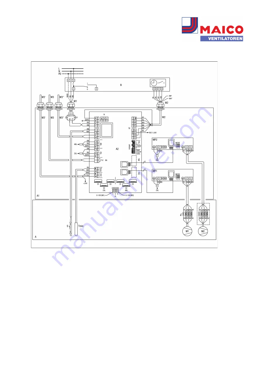
Maico WR 600 Wiring Diagram Download Page 9

WIRING DIAGRAM

WR 600

Version: 2019-05-22 - MAICO VENTILATOREN, www.maico-fans.com - We are not responsible for mistakes or printing errors and retain the
right to make technical modifications without giving prior notice

Page 9

Wiring diagram for WR 600 ventilation with RLS 2 F room air control

Summary of Contents for WR 600

Page 1: ...n t e i l L1 N Z u l u f t N L 1 L 1 N L 1 L 1 N 1 2 3 4 5 6 7 8 9 1 0 CO2 BDE On Off Temp 2 4 V GY PK WH BN BN BU GNYE BN GNYE BU WH BU A2 W2 BN WH T y p 0 10V M1 0 10V M2 5 3 1 GNYE BU BN N e t z A...

Page 2: ...r volumetric flow ventilation level 2 S3 blue setting potentiometer for supply air volumetric flow ventilation level 3 S1 red setting potentiometer for exhaust air volumetric flow ventilation level 1...

Page 3: ...d Jumper 10 CO2 set B1 room air control RLS 1 WR CO2 CO2sensor SKD W1 230 V AC connecting cable W2 control cable for room air control W3 connecting cable for external CO2sensor to be supplied by the c...

Page 4: ...his purpose This blocks the room air control RLS 1 WR The LED display goes out The unit is only released again when the differ ential pressure controller switches the fans back on The ventilation unit...

Page 5: ...rols can be connected to the ventilation unit No CO2 sensor should be connected if several room air controls are connected A1 electrical terminal box WR 600 A2 control circuit board Jumper setting Fac...

Page 6: ...back to the previously selected ventilation level If you switch manually or using the timer from ventilation level 3 to level 2 or 1 this deactivates the automatic function of the hygrostat temporaril...

Page 7: ...O VENTILATOREN www maico fans com We are not responsible for mistakes or printing errors and retain the right to make technical modifications without giving prior notice Page 7 Wiring diagram for WR 6...

Page 8: ...entilation level 2 S3 blue Potentiometer adjuster ventilation level 3 Exhaust air S1 red Potentiometer adjuster ventilation level 1 S2 red Potentiometer adjuster ventilation level 2 S3 red Potentiomet...

Page 9: ...O VENTILATOREN www maico fans com We are not responsible for mistakes or printing errors and retain the right to make technical modifications without giving prior notice Page 9 Wiring diagram for WR 6...

Page 10: ...ventilation level 2 S3 blue Potentiometer adjuster ventilation level 3 Exhaust air S1 red Potentiometer adjuster ventilation level 1 S2 red Potentiometer adjuster ventilation level 2 S3 red Potentiome...

Page 11: ...ation unit switches back to the previously selected ventilation level If you switch manually from ventilation level 3 to level 2 or 1 this deactivates the automatic function of the hygrostat temporari...

Page 12: ...rature can be adjusted manually using the setting wheel at the TH 10 The air flow controller sensor S1 must be installed in the direction of flow at least 30 cm ahead of the electrical air heater The...

Reviews: