


18
Display or
selection
value
Description
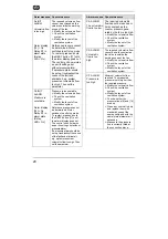
m³h K3?
xxxx
Define setpoint for constant
volumetric flow, e.g. for
nighttime operation (only if
switching contact K3 has
+12 V applied).
PRESS.
ALARM? x
Compressed air alarm
On = Y(es) / Off = N(o)
"Y":
If the reference pressure
is exceeded, the alarm display
[15] lights up red.
"N":
END CONFIG.
SETUP menu ends. The
operating display appears.
P FAN
xxx Pa
Enter permissible pressure
increase at the reference
volumetric flow, e.g. in the
case of filter contamination.
INIT Pa
REF? x
"Y":
Start reference
volumetric flow input.
"Y":
END CONFIG.
SETUP menu ends. The
operating display appears.
m³h INIT
xxxx
Input maximum reference
volumetric flow. The reference
pressure is calculated.
Pa REF
INIT.
—
xxxx m³h
xxxx Pa
Fan starts.
The calculated static pressure
value is saved, approximately
one minute after
the initialised volumetric flow
is reached in the fan.
The current pressure and
volumetric flow are displayed.
END
CONFIG
SETUP menu ends. The
operating display appears.
Tab. 3: CAs menu items
Always replace the housing cover and
screw it in place at the end of the
parameter setting process.
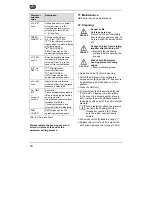
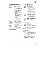
11. Maintenance
GRD units require no maintenance.
12. Cleaning
DANGER
Danger to life.
Unit is powered up.
Disconnect the unit completely
from the mains power supply. To
do this, switch the service switch
off.
DANGER
Danger of injury from rotating
impeller after switching off!
Wait until the impeller is
stationary before opening the
housing.
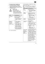
CAUTION
Risk of cuts from metal
housing plates with sharp
edges.
Wear protective gloves.
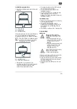
Remove unit roof [1] before cleaning.
Switch the GRD unit off by setting the
service switch [8] to position "0" and secure
it against being switched back on with a
padlock.
Clean the GRD unit.
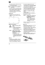
Check whether the pressure lines [6] and
[14] are dirty. Clean any line that is dirty.
In the case of pressure lines that are very
dirty, replace them with standard hoses of
the same quality and with the same internal
diameter.
When replacing, attach the pressure
line [6] to the housing [4] with a
threaded connection [6.1]. Make
sure the rubber seal is correctly
seated.
Set service switch [8] back to position "I".
Replace the unit roof and fix in place with
both rings, tightened to a torque of 30 Nm.
GB
i