


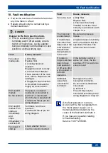


18. Fault rectification
31
18. Fault rectification
● Call on the services of a trained electrician
any time there is a fault.
● Repairs should only be carried out by a
trained electrician.
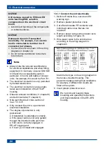
DANGER
Danger to life from electric shock.
Prior to accessing the connection
terminals, switch off all supply circuits.
Switch off mains fuse, secure against
being accidentally switched back on and
position a visible warning sign.
Fault
Cause, measure
Fan output
inadequate.
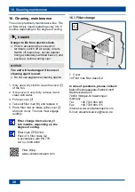
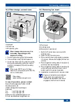
● Dirty filter.
Replace filter.
● Locking hook not
engaged.
Engage fan insert correctly.
● Incorrect duct diameter.
Check diameter of the main
duct, refer to diagram in the
catalogue.
● Supply air cross section
is too small. Increase the
supply air cross section.
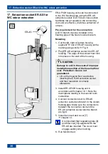
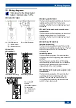
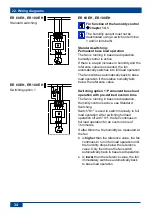
EVZ and EH
models:
No fan overrun.
The power on external
conductor L connected to
terminal 1 is interrupted
when the fan is switched off.
Connect the fan as per the
wiring diagram.
EVZ and EH
models: Fan
starts up
immediately
and
stops
immediately if is
switched-off.
Terminals 1 and 3 are
reversed.
Connect the fan as per the
wiring diagram.
Fan doesn’t
start up
Check whether the fan
insert is correctly inserted.
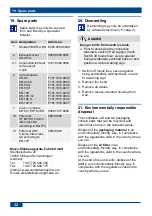
Fault
Cause, measure
Fan is too loud. ● Dirty filter.
Replace filter.
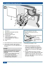
● Fan insert incorrectly
installed. Insert fan insert
correctly in accordance with
chapter 14.2.
The main duct
is undersized.
Re-calculate pressure
losses.
H model does
not switch from
base load to full
load operation
despite there
being moisture
in the room.
A rapid increase in humidity
was not reached within the
specified 2 minutes. The
reference value is reset.
H mode no
longer switches
back to base
load operation
or off even after
a long period in
full load
operation.
If the humidity control is
active for 1 hour, the fan
switches off. The reference
value is reset.
Additional
consumers
connected to
terminal 4.
Damage to the unit if
connected incorrectly.
Do not connect additional
consumers
to terminal 4.
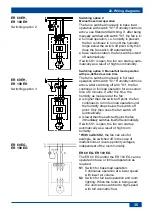
The unit may only be
connected according to the
wiring diagrams in chap. 22.
If the fault persists or reoccurs:
Disconnect the fan completely from
the mains power supply. Let a
trained electrician determine the
cause of the fault and eliminate it.
If you have any question relating
to troubleshooting:
Service: +49 7720 6940.
Summary of Contents for ER-UP/GH
Page 2: ...2 1...


