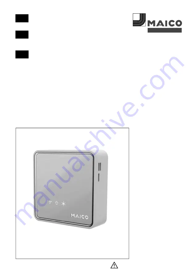
Maico EAQ 10/3 Mounting And Operating Instructions Download Page 1


Montage- und Betriebsanleitung 

Luftqualitätsregler


Mounting and operating instructions


Environmental air quality controller 


Instructions de montage et mode d’emploi 


Régulateur de qualité d´air


EAQ 10/3 


w w w . m a i c o - v e n t i l a t o r e n . c o m  

DE 

VENTILATOREN

GB 

FR 

Summary of Contents for EAQ 10/3

Page 1: ...itung Luftqualitätsregler Mounting and operating instructions Environmental air quality controller Instructions de montage et mode d emploi Régulateur de qualité d air EAQ 10 3 www maico ventilatoren com DE VENTILATOREN GB FR ...

Page 2: ...ge Informationen und Tipps 1 Sicherheitshinweise Lesen Sie diese Montage und Betriebsanleitung aufmerksam durch bevor Sie die Einheit montieren oder in Betrieb nehmen Folgen Sie den An weisungen Übergeben Sie diese Anleitung zur Aufbewahrung an den Besitzer Veränderungen und Um bauten am Gerät sind nicht zulässig und entbinden den Hersteller von jeglicher Gewährleistung und Haftung Personen auch K...

Page 3: ...leistung und Haftung Bestimmungsgemäße Verwendung Luftqualitätsregler zur Regelung der Frischluftzufuhr abhängig von der Raumluftqualität Verwendung nur in Wohnräumen Vorhersehbare Fehlanwendungen Gerät auf keinen Fall einsetzen In der Nähe von brennbaren Materialien Flüssigkeiten oder Gasen In explosionsgefährdeten Bereichen Für sicherheitstechnische Anwendungen In der Umgebung von Silikonen und ...

Page 4: ...Potentiometer ganz nach rechts gedreht wird wird die jeweilige Messgröße nicht ausgewertet VOC oder Feuchte Relais Max 0 5 A 36 VAC VDC Schaltpunkt VOC ca 1300 ppm CO2 Äquivalent 500 ppm einstellbar Schaltpunkt Feuchte ca 50 relative Feuchte 20 r F einstellbar 4 Montagehinweise Bei der Montage des Sensormodules ist zu beachten dass dieses eine möglichst ungehinderte Luftzirkulation hat um die Mess...

Page 5: ...rsichtig ca 6 mm tief in den mittleren unteren Gehäuseschlitz um die innere Verschlussklammer zu lösen Nun kippen Sie das Gehäuse im unteren Bereich nach vorne 3 Montagelöcher durchstoßen und Markierungen an der zur Montage vorgesehenen Wand erstellen Achten Sie darauf dass die Kabeleinführung oben liegen muss 4 Gehäuseunterteil mit min 2 Schrauben am Montageort befesti gen Geeignetes Befestigungs...

Page 6: ...tartsequenz liegt am 0 10 Volt VOC Ausgang für etwa 2 Minuten eine konstante Spannung von 3 0 Volt DC an danach geht der Sensor in den Messbetrieb das Ausgangssignal ist dann abhängig von der Luftgüte 4 Durch die Montage warme Hände o Ä wurde das Gerät ggf erwärmt Warten Sie etwa 15 Minuten bis sich das Gerät an seine Umgebungstemperatur angepasst hat und reelle Werte für die Luftfeuchtigkeit vera...

Page 7: ...and operating instructions carefully before starting installation or commissioning work Installation is only permitted when carried out by trained specialists Follow the instructions Pass these instructions onto the owner for safe keeping Modifications and alterations to the ventilation unit are not permitted and release the manufacturer from any guarantee obligations and liability People includin...

Page 8: ... be operated using the voltage and frequency shown on the rating plate Only operate the unit when it is completely installed Modifications and alterations to the unit are not permitted and release Maico from any guarantee obligations and liability Intended use Air quality controller for controlling fresh air supply dependant on the room air quality Only for use in living areas Predictable misuse T...

Page 9: ...ntact can also be used and its switching point set using a potentiometer If a potentiometer is completely turned to the right the respective measurement values are not analysed VOC or humidity Relay Max 0 5 A 36 VAC VDC VOC switching point ca 1300 ppm CO equivalent 500 ppm adjustable Humidity switching point ca 50 rel humidity 20 r h adjustable 4 Mounting instructions When installing the sensor mo...

Page 10: ...iver or suitable object to press approx 6 mm down in the centre bottom housing slot to release the inner locking clamp and tilt the bottom part of the housing forwards 3 Push through mounting holes and produce marks on the wall intended for installation Note that the cable entry must be at the top 4 Use min 2 screws to secure the bottom part of housing to the installation location Suitable mountin...

Page 11: ...e of 3 0 Volt DC at the VOC output for approx 2 minutes Then the sensor switches to measuring mode the output signal depends on the air quality 4 The unit may have been heated by installation warm hands etc Wait around 15 minutes until the unit has adapted to the ambient temperature and real values for the air humidity can be determined 7 Disposal Not in domestic waste The unit contains in part ma...

Page 12: ...ironnement Symbole INFO pour informations et conseils importants 1 Consignes de sécurité Prière de lire attentivement les présentes instructions de montage et le mode d emploi avant de monter l unité ou de la mettre en service Le montage est exclusivement réservé à des professionnels autorisés Suivez les instructions Confiez les présentes instructions au propriétaire qui devra les conserver Les mo...

Page 13: ...ques dus à des installations et réglages erronés et les dangers en résultant Ne raccorder l appareil qu à une installation électrique permanente voir Chapitre 5 Branchement électrique Utiliser exclusivement l appareil à la tension et à la fréquence indiquées sur la plaque signalétique N utiliser l appareil qu après son montage complet Les modifications et trans formations apportées à l appareil so...

Page 14: ...Borne de raccordement Fiche avec bornes à vis pour 0 25 1 5 mm Type de protection IP 30 Poids 78 grammes Dimensions L l h 80x80x25 mm Relais En fonction du COV et de l humidité relative il est également possible d utiliser un contact de commutation libre de potentiel dont le point de commutation sera réglé par le potentiomètre respectif Si l un des potentiomètres est tourné vers la droite jusqu en...

Page 15: ...e J YSTY 0 6 0 8mm 4 fils En utilisant le relais sous certaines conditions 5 fils au moins 2 Ouverture du boîtier des détecteurs Avec un tournevis ou autre objet approprié appuyez avec précaution 6 mm env dans la fente centrale inférieure du boîtier pour libérer l agrafe de fermeture intérieure et basculez le boîtier vers l avant au niveau du bas 3 Percer les trous de montage et marquer des repère...

Page 16: ... vert l ordre dépend ici de la position du relais du réglage Après la séquence de démarrage la sortie COV 0 10 volts est soumise pendant 2 minutes environ à une tension constante de 3 0 volts DC Le détecteur passe ensuite en mode de mesure le signal de sortie dépend alors de la qualité de l air 4 Le montage provoque le cas échéant un réchauffement mains chaudes ou similaire de l appareil Attendez ...

Reviews: