


25
Maxuum III Digital Electronic Indicator 2239028 Rev D
4.0 OPERATION
The Maxum III indicator is shipped with its battery installed.
There is no power switch; the Indicator is always ON However,
when the Spindle is fully extended (at rest) or fully depressed,
the Indicator is in its Sleep Mode, and only the ‘+’ or ‘-’ sign is
displayed.
4.1 Operating the Maxum III
Fully depress the Spindle once, and hold. The opposite sign
appears. This assures that the Maxum III Indicator is operational.
The in/mm icon also appears when the unit is active.
A Maxum III Indicator can be mounted in a gage or fixture
using an optionally available back., or the Indicator can be stem-
mounted. The ‘Canister Style’ Digital Transducer must be
mounted by its stem only. Do not mount this transducer by its
1.00 in / 25.4 mm diameter barrel. Mounting brackets and racks
are available to hold Digital Transducers and Indicating Units for
use with fixture gages.
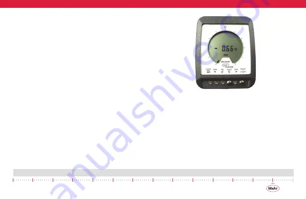
4.1.1 Off-Scale
Whenever the digital reading exceeds the analog display range,
the last single analog display graduation will blink. This signals
that the remaining digital range is still operational, however the
analog range has been exceeded.
Figure 18 -
Indicator shown in Off-Scale condition
4.1.2 Over-Range
Over-Range occurs when digital range has been exceeded.
When the digital range is exceeded, the Indicator is in an ‘over-
range’ condition and is indicated by a blank display that shows
both the polarity sign and the in/mm units icon. Unit is still
active and not to be confused with the ‘Sleep mode’ condition,
which only shows the polarity sign.
Whenever this occurs in the Enhanced Mode, the spindle must
be returned to an on scale value, which is indicated by a single


