24
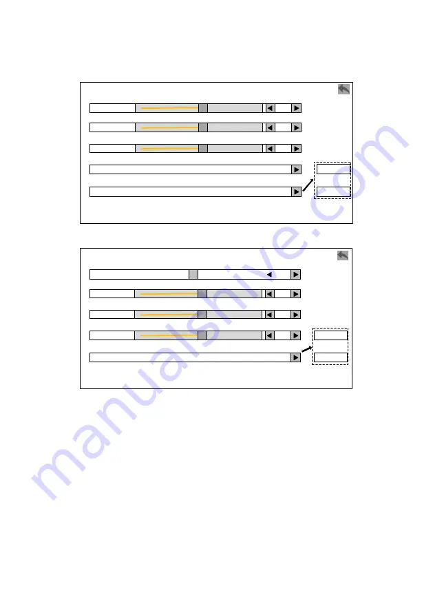
Layer 1~4 picture setting:
Brightness
Layer1 Picture Setting
50
Color temp
Reset
Contrast
Saturation
Cancel
Layer 1~4 color temperature setting:
Color Temp
6500K
R
128
G
Layer 1
B
Page 1: ...LED W4000 User manual V2 0 Before using this video processor please read this manual carefully and keep it for reference in the future 8k 2K Video Processor...
Page 2: ...nic mechanical photocopying record or other way for any business and profitable purpose The product specifications and information mentioned in this manual is just for reference will not give prior no...
Page 3: ...7 Default status introduction 18 Main menu introduction 20 Main menu 22 Picture setting menu 23 Output setting menu 26 Input setting menu 33 Layers setting menu 39 Save Load 47 EDID setting 49 COMM se...
Page 4: ...Warranty Description 79 Machine warranty 79 Non warranty 79...
Page 5: ...instructions when you install and operate the product Trademark credit VGA and XGA is a registered trademark of IBM VESA is a Video Electronics Standards Association s trademark HDMI HDMI mark and Hi...
Page 6: ...n 3 layers and 3 layers Backup mode input signal hot backup or manual backup and seamless switching between input signal or tile input Multi machine cascading mosaic synchronously and Take seamless sw...
Page 7: ...e Corresponding model Description Input module Expand one 4K 60Hz input modules LED W4000 DH The 4K 60Hz input module includes one DP1 2 input and one HDMI 2 0 input one HDMI loop out Either DP or HDM...
Page 8: ...ad Before you operate any hardware please turn off the LED video processor s power and to set you on the electrostatic by touching the ground surfaces Please use the processor in clean dry and ventila...
Page 9: ...stage performances theaters and TV stations etc The load capacity of LED W4000 series is several times of normal video processor support EDID management and customized output resolution single process...
Page 10: ...rent setting Select the menu and adjust INPUT MUX TILE 2 TILE 1 INPUT 6 RIGHT INPUT 6 LEFT INPUT 5 RIGHT INPUT 5 LEFT INPUT 4 INPUT 3 INPUT 2 Shortcut button of input configuration Combined input 2 Nu...
Page 11: ...hortcut button of layer size Freeze the output image The selected layer fades in The selected layer fades out LOGO On Off TAKE LOAD PRESET SAVE PRESET ZOOM BRIGHT LEVEL In switch mode fade in and out...
Page 12: ...8 LED W4000 2DH LED W4000 The rear panel...
Page 13: ...o use at one time INPUT 3 DVI 1 DP 1 HDMI 1 choose one of the three to use at one time INPUT 4 DVI 1 DP 1 HDMI 1 choose one of the three to use at one time INPUT 5 expanded DP 1 HDMI 1 HDMI LOOP 1 cho...
Page 14: ...10 Control interface RJ45 1 Network cable port control the machine by LAN USB 1 USB upgrade port upgrade the machine by a USB flash drive RS232 1 RS232 port GENLOCK IN 1 OUT 1 Genlock port...
Page 15: ...pports EDID management DP1 1 4 Supports 3840 1080 60Hz 3840 2160 30Hz and EDID management HDMI1 4 3 Supports 3840 1080 60Hz and EDID management SDI SDI IN 1 SDI LOOP 1 480i 60Hz 576i 50Hz 720p 60HZ 10...
Page 16: ...1280 720 59 94Hz 1024 1280 60Hz 1920 1080 60Hz 2048 1920 60Hz Customized output resolution bandwidth optimization Horizontal resolution up to 2048 pixels Vertical resolution up to 3840 pixels HDMI 2 2...
Page 17: ...13 Machine specification Input power 100 240V AC 50 60Hz 0 6A Operating temperature 0 45 Dimensions 482 6 446 3 92 5mm L W H Net weight 6 7KG Power consumption 90w...
Page 18: ...ill be displayed on the LCD screen when the user has no operation or the operation has timed out If operating with the buttons on the front panel the corresponding menu will be displayed on the LCD sc...
Page 19: ...ckwise to move the cursor down or to the right Move the cursor to the item to be adjusted press the knob or confirm button to enter the setting mode At this time turn the knob counterclockwise to decr...
Page 20: ...output mode INPUT area This area includes 11 buttons INPUT 1 INPUT 2 INPUT 3 INPUT 4 INPUT 5 LEFT INPUT 5 RIGHT INPUT 6 LEFT INPUT 6 RIGHT TILE 1 TILE 2 LOGO Among them INPUT 5 LEFT INPUT 5 RIGHT INP...
Page 21: ...Fade out the selected layer FADE IN Fade in the selected layer FREEZE Freeze current image SIZE Enter resize menu interface TEST PATTERN Open the test pattern interface BRIGHT LEVEL Open the brightnes...
Page 22: ...esolution 1920 1080 60 00Hz Here is the instruction of the above Instruction Input 1 1920 1080 Input 1 and current input signal resolution the right side is the 3 input sources corresponding to input...
Page 23: ...ht side is the 2 input sources of Input 6 If this expansion board is not added it will not be displayed here Output mode Display the current output mode of the processor DVI mode or HDMI mode Output r...
Page 24: ...tate the knob to select each menu or touch on the corresponding menu Adjust parameters When the right end of the item is a number or option parameters press the knob to select the parameters whirling...
Page 25: ...indicates that the modified parameters is confirmed indicates that backspace to delete the entered number Thenumeric keypad is shown below H act Customized Resolution 3840 V act 1080 FPS 60 Accept Adv...
Page 26: ...ill show as below Totally 10 items selected by rotate the knob The color of selected item is yellow otherwise is white Then press OK enter the item press to return We can also touch the LCD screen to...
Page 27: ...agement Layer1 Picture Setting Layer2 Picture Setting Layer3 Picture Setting Color management Color Scenes Color Management Disable Gamma OFF Disable Low Gray Suppress Red Enhance Blue Vivid Picture P...
Page 28: ...cture setting Brightness Layer1 Picture Setting 50 Color temp Reset Contrast 50 Saturation 50 Cancel Reset Layer 1 4 color temperature setting Color Temp Color Temp 6500K Reset R 128 G 128 Cancel Rese...
Page 29: ...lt Gamma Turn on off Gamma range 0 0 5 0 Layer 1 4 Picture Setting Brightness range 0 100 50 by default Contrast range 0 100 50 by default Saturation range 0 100 50 by default Layer 1 4 Color Temp 400...
Page 30: ...ode resolution Resolution Page 1 1 1024 768 60Hz 1280 1024 60Hz 1600 1200 60Hz 1920 1200 60Hz 1024 768 120Hz 1280 720 59 94Hz 1280 720 60Hz 1600 1200 60Hz Rdc 1680 1050 60Hz 1920 1080 59 94Hz 1920 108...
Page 31: ...ution Advanced 1920 H tot 2200 H sync 44 Hbp 148 V act 1080 FPS 60 V tot 1125 V sync 6 1920 1 2 3 4 5 6 7 8 9 0 C OK Vbp 35 Apply 148500000 Hz HDMI mode resolution Resolution 1920 1080 60Hz 1920 1080...
Page 32: ...t Customized Resolution 3840 V act 1080 FPS 60 Accept Advanced 3840 1 2 3 4 5 6 7 8 9 0 C OK Cancel Continue H act Customized Resolution Advanced 3840 H tot 4400 H sync 32 Hbp 80 V act 1080 FPS 60 V t...
Page 33: ...example Output Panel Config Panel Layout Window HDMI1 Window OFF Reset H Pos 0 Width V Pos 0 Height HDMI2 ON 3840 1080 HDMI1 Panel Layout Window Horizontal H Pos 0 V Pos 0 HDMI2 Vertical H Pos 0 V Pos...
Page 34: ...DMI 2 output as preview Output monitor will have preview in red HDMI1 as program output when output resolution under 4K 1K it support 3 layers preview switching to 3 layers while on 4K 2K only support...
Page 35: ...same so does 2 groups of HDMI outputs but the size of output window can be different Notice 3 Please use with caution of the resolution with over 60 Hz or super wide high pixels the backend device ma...
Page 36: ...bandwidth range under 10BIT mode the load is reduced by about a third recommend use on 4K 1K 60Hz 10BIT range 3 Signal only input from input 5 or 6 input port 4 HDR function on this machine work as B...
Page 37: ...tal 2200 1125 02 Input1 DP No Signal 03 Input1 SDI No Signal 04 Input2 DVI 1920 1080 Total 2200 1125 05 Input2 DP No Signal 06 Input2 HDMI No Signal 07 Input3 HDMI No Signal 08 Input3 DP No Signal Inp...
Page 38: ...fig Input1 DVI Input2 DP Input3 DP Input4 HDMI Input5 HDMI Input6 NONE TILE Keys Config Combine multiple input signals to a Tile TILE 1 TILE Keys Config Input 1 Input2 TILE 2 Input 1 DVI 1920 1080 Edi...
Page 39: ...nput 1 Function ON Reset Match To Input H Pos 0 Width H Range V Pos 0 Height V Range 1920 1080 1920 1080 Digital Input Color Range Digital Input Color Range When RGB Info Available Input 1 Auto Auto L...
Page 40: ...t sources on the right side The left side of each input source green strip means valid signal red strip means no signal White and yellow text yellow means this source is the input MUX of corresponding...
Page 41: ...tually restrictive under cropping Function off Turn off the image crop function Function on Turn on the image crop function reset Reset the parameters of image crop Match input signal Match the image...
Page 42: ...support 4 2K 1K 2 2K 1K or 2 2K 2K range input signal combine to a Tile 2 On switcher mode support 2 2K 1K range input signal combine to a Tile 3 Only same resolution signals could be combined to a T...
Page 43: ...mosaic mode support layer quick setting Duration LAYERS Mosaic LVL 2 Zoom Layer Configuration Layer Quick Setting Layer Quick Setting Auto layout Horizontal Layer Quick Setting Layer 1 Vertical Windo...
Page 44: ...Layer Configuration OFF H Pos 0 Width V Pos 0 Height Layer 2 Layer 3 Layer 4 ON R R R R 3840 1080 Layer Property Alpha Layer Property 64 Chroma Keyr Layer 1 R Low Chroma Keyer 0 Layer 1 Only Show Col...
Page 45: ...lack Blue On Black Red On White Green On White Blue On White Black On White White On Black Green Screen Matting Blue Screen Matting Zoom layer zoom function Function OFF Zoom Function ON Reset Match T...
Page 46: ...djust Duration LAYERS HDMI SW Cut Zoom Layer configuration Layer 1 Layer Configuration OFF H Pos 0 Width V Pos 0 Hight Layer 2 Layer 3 ON 3840 1080 Function OFF Zoom Function ON Reset Match To Input H...
Page 47: ...up Disable Disable Enable TAKE Together Disable Layer configuration select input use to main layer and backup layer select input signals Layer Configuration Input Select H Pos 0 Width V Pos 0 Height I...
Page 48: ...operate buckle color setting the range by progress bar and number key That is control the upper and lower limits of the Red green blue color right side will display current setting quick setting up t...
Page 49: ...input signal According the input signal resolution matching corresponding vertical horizontal datum Layer zooming parameters Adjust zooming layer s size position datum Duration duration of preview and...
Page 50: ...work as preview output has red preview indicate HDMI1 is main output when output resolution is 4K 1K and below support 3 layer to 3 layer preview switch and LAYER1 support Full roaming LAYER2 only su...
Page 51: ...Accept Preset Source Program Preview Program Clear All Preset Save Preset Mosaic 1 2 3 4 5 6 7 8 9 10 11 12 13 14 15 16 17 18 19 20 Saving Finished Preset 1 Will Be Overwritten Cancel Continue Load Pr...
Page 52: ...te 4 The Save Preset Channel menu will only appear on switch HDMI mode Save Preset Mosaic mode Shows which currently saved preset is saved in which operating mode in this processor 1 20 It can save 20...
Page 53: ...6 can be set except SDI You can enter the EDID configuration detailed operation menu to set the EDID by knob selecting or input the number on touch screen DVI Input 1 Indicates the input serial number...
Page 54: ...o different computers and different graphics cards it may need to restart the computer or plug in the signal cable In the resolution output of the computer select the corresponding resolution our tech...
Page 55: ...the gateway then the connection is successful Communication setting By modifying the IP address and gateway of the processor it is convenient for the computer to connect to the processor through the...
Page 56: ...g Mode Mosaic Sync Lock Setting FreeRun FreeRun Genlock Logo Screen Touch Enable Mosaic Backup Enable Disable HDMI Switcher Lock To LAYER1 Misc Page 2 2 Date Time Schedule Task Factory Reset Status In...
Page 57: ...500 mv 1484 mv 3 voltage STD 1000 mv 996 mv 4 voltage STD 1200 mv 1116 mv 5 voltage STD 12000 mv 11146 mv 6 voltage STD 3300 mv 3402 mv 7 voltage STD 5000 mv 4874 mv Logo This menu is slightly differe...
Page 58: ...DMI switcher mode Logo Not Saved Load Save New Logo Layer Start Layer 1 Layer 1 Layer 2 Layer 3 Program Channel Program Preview Delete Cancel Delete Logo Logo Saving 3840 1080 For HDMI SW Load Save Ne...
Page 59: ...e New Logo Start Delete Cancel Delete 50 Date Time Date Date Time 2018 02 24 Time Edit Edit 20 41 38 Saturday Reset Apply 1 2 3 4 5 6 7 8 9 0 C OK Schedule Task Schedule Task 2018 02 24 20 46 09 Task...
Page 60: ...Mosaic 1 2 3 4 5 6 7 8 9 10 11 12 13 14 15 16 17 18 19 20 Date Task Config 2019 01 01 Time Skip Cancel 1 Frequeny 1 Select Preset Apply Date Task Config 2019 01 01 Time Skip 1 Frequeny 1 Select Prese...
Page 61: ...eset Apply Skip Only Once Every day Period Date Task Config 2019 01 01 Time Skip Cancel 1 Frequeny 1 Select Preset Apply Select Preset 1 2 3 4 5 6 7 8 9 10 11 12 13 14 15 16 17 18 19 20 Factory Reset...
Page 62: ...the prompt box also the resolution of the currently saved logo and the applicable working mode After the logo is successfully saved the prompt box displays that the logo has been loaded and displays t...
Page 63: ...the current task performs the action Frequency Select the frequency at the current task performs the operation invalid single daily and periodic Select Preset Select the preset of the current task ex...
Page 64: ...e current output In the Layer1 screen selecting Save Logo will overwrite the previously saved Logo Note 4 After clicking to start saving the logo the machine will not be able to operate Please wait fo...
Page 65: ...reen Pixel Grab Database Needs To Be Rebuilt Warning Pattern Generator Cancel Continue 50 Test Pattern For LCD Screen To Select Patterns To Show The Hint To Hide The Hint To Quit Current Menu Touch He...
Page 66: ...VI1 Window Pixel Color H Pos 0 V Pos 0 DVI2 DVI3 DVI4 0 0 0 HDMI1 Window Pixel Color H Pos 0 V Pos 0 HDMI2 0 0 0 Capture selected pixel colors DVI1 Window Pixel Color H Pos 145 V Pos 616 DVI2 DVI3 DVI...
Page 67: ...The database needs to be rebuilt When after the processor factory reset the submenu will pop up Click Continue to use the card Test Pattern For LCD Screen Test whether the LCD panel of this unit is di...
Page 68: ...English Set the display language of the menu system to English Simplified Chinese Set the display language of the menu system to simplified Chinese Traditional Chinese Set the display language of the...
Page 69: ...ach group of 3 signals choose one of three to use each time Total SDI 1 HDMI 3 DVI 4 DP 4 Resolution specifications SDI 3G SDI 1080P i and below HDMI DVI DP support 4K 1K 60Hz range EDID Expanded inpu...
Page 70: ...a port Output port 12 channel divide into 2 groups First group HDMI1A 1B DVI1A 1B DVI2A 2B Second group HDMI1A 1B DVI1A 1B DVI2A 2B DVI HDMI alternative one of two to use each time Control area Interf...
Page 71: ...ndby interface LAYER area Layer 1 Layer 2 Layer 3 Layer 4 Corresponding to the four layers of the device short press to select the layer long press for about 3 seconds to open or close the layer FULL...
Page 72: ...utton Signal selection method First select a layer layer1 4 then select an input signal FUNCTION area Fade Out Fade In fade out and fade in buttons of the currently selected layer It can be used with...
Page 73: ...configure the input signal Set one of the signals in each groupas input or press the INPUT MUX button on the front panel to enter the menu PICTURE OUTPUT INPUT LANGUAGE EDID LAYERS COMM SAVE LOAD MISC...
Page 74: ...utput aliquot unequal load relationship TILE 1 TILE Keys Config Input 1 Input2 TILE 2 Input 1 DVI 1920 1080 Edit Edit Undefined Input 2 DP No Signal Input 3 DP No Signal Input 4 HDMI No Signal Input 5...
Page 75: ...er Output setting in the main menu select the Mosaic mode use DVI or HDMI output and output resolution of single output port Output Mode Output DVI Mode Resolution 1920 1080 60 00Hz Window HDMI Settin...
Page 76: ...ontally vertically and 4 identical squares on DVI output Layer 1 Layer Configuration OFF H Pos 0 Width V Pos 0 Height Layer 2 Layer 3 Layer 4 ON R R R R 3840 1080 Layer Property 3 Enter the LAYERS set...
Page 77: ...aic to the output horizontal vertical or 4 identical squares layout The LED W4000 output each layer is independent By setting the size of the output window and the layout of the output to matches the...
Page 78: ...MI Switcher Mosaic Backup HDMI Switcher 2 Enter Layers Setting menu and select Layer Configuration or directly press the SIZE button to enter this operation interface and adjust the size of each layer...
Page 79: ...through the knob and OK button Use the TAKE button to switch between main output and preview Save Preset Mosaic 1 2 3 4 5 6 7 8 9 10 11 12 13 14 15 16 17 18 19 20 Saving Finished Preset 1 Will Be Ove...
Page 80: ...76 make preset load and switch operations D Saved presets the number key is highlighted 4 Duration there are CUT and LEVEL1 3 optional Duration LAYERS HDMI SW Cut Zoom Layer configuration...
Page 81: ...ode Backup Mosaic Backup HDMI Switcher 2 Adjust the Window menu set the actual pixel loaded on each output port and the mosaic mode of the output port refer to the setting method in the mosaic mode 3...
Page 82: ...ckup the main display layer is always at the top backup is at the bottom 3 Automatic backup is disabled by default When this function is enabled if W4000 detects that the input signal of the main disp...
Page 83: ...d collisions produced besmirch or surface scratches and other abnormal using causes of malfunction or damage Demolition machine or modification which is not to be agreed by our company Using in the no...