background image

Description

F50 Flow Switches are utilized, in horizontal lines, to sense
the start or stop of liquid flow in oil, chemical, gas, and
water lines.

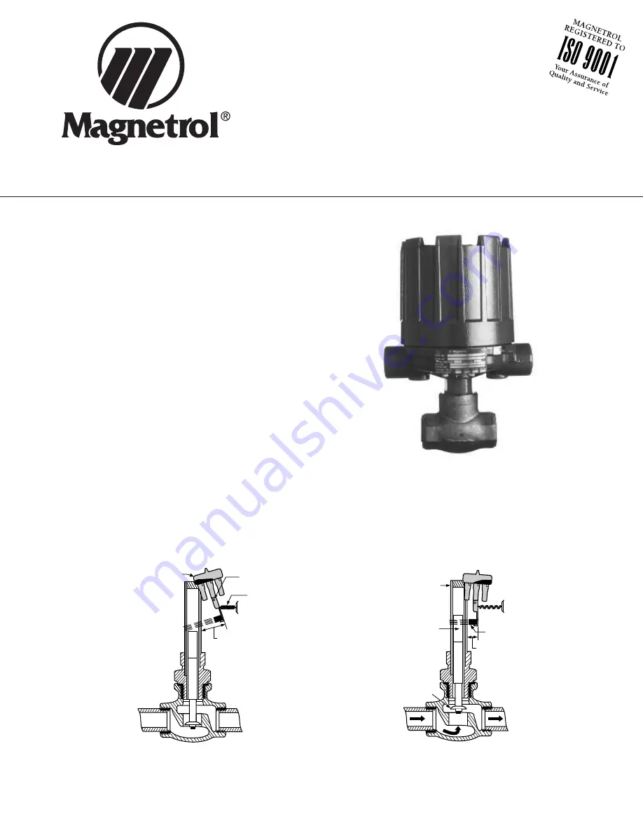
Principle of operation

The rate of flow through the valve body raises or lowers the
disc. This in turn raises or lowers the magnetic sleeve, with-
in its sealed non-magnetic enclosing tube. On an increasing
flow rate, the magnetic sleeve rises into the field of the per-
manent magnet, located outside the enclosing tube, actuat-
ing the attached switch mechanism. When the flow rate
drops, below the rate for which the flow disc is calibrated, a
reversal of this action occurs.

Operating cycle

On an increasing flow rate, the flow disc moves the attrac-
tion sleeve up within the field of a switch magnet, drawing it
in tightly to the enclosing tube. This causes the switch to
make or break an electrical circuit. When the flow rate
drops, below the rate for which the flow disc is calibrated,
the attraction sleeve is pulled downward until, at a predeter-
mined low flow rate, the switch magnet releases and swings
outward, away from the enclosing tube, causing a reversal
of the switching action.

Figure 1

Figure 2

5

6

4

Mercury switch

Swing out

position

Tension

spring

Pivot

No flow

position

5

6

4

Enclosing tube

(Non-magnetic)

Swing in

position

Sleeve

(magnetic)

Magnet

Flow disc

Position with

actuating flow

present

F50 Flow Switch

Instruction Manual and Parts List

Summary of Contents for F50

Page 1: ...s action occurs Operating cycle On an increasing flow rate the flow disc moves the attrac tion sleeve up within the field of a switch magnet drawing it in tightly to the enclosing tube This causes the...

Page 2: ...Agency approvals Model number construction F50 2 Basic part number materials of construction and pipe line size Actuating flow rate Switch mechanism and enclosure GENERAL INFORMATION 2 Model identific...

Page 3: ...hru F Snap Switches 121 3 4 or 1 A thru F BNP BNT Bronze 11 2 or 2 A thru D DPDT E and F BNQ BNS S S 3 4 thru 2 A thru F 3 4 or 1 A thru F CKP CKT Bronze 11 2 or 2 A thru D SPDT E and F CKQ CKS Series...

Page 4: ...ctions NOTE For proper performance a straight pipe run 12 pipe diameters upstream and three pipe diameters downstream of the switch is recommended Usually the first indication of improper operation is...

Page 5: ...eumatic switches air or gas operat ing medium lines subjected to vibration may eventu ally crack or become loose at connections causing leakage Check lines and connections carefully and repair or repl...

Page 6: ...29 NEMA 4X 7 9 151 108 NEMA 4X 7 9 5 93 4 29 10 75 4 60 Group B 151 108 273 116 NEMA 1 4 70 5 00 9 44 4 44 Pneumatic 119 127 240 113 NOTE 1 For NEMA 4X allow 8 00 203 overhead clearance for cover rem...

Page 7: ...7127 001 32 7127 003 32 7127 002 32 7108 001 32 7109 001 32 7109 002 12 Lock Nut 10 2107 002 10 2107 003 10 2107 002 10 2107 003 13 Flow Disc Specify complete model number Switch Mechanism Series Refe...

Page 8: ...gnetrol local representative or by contacting the factory Please supply the following information 1 Company Name 2 Description of Material 3 Serial Number 4 Reason for Return 5 Application Any unit th...

Reviews: