background image

F10

Vane type 

flow switches

®

INSTRUCTION MANUAL AND PARTS LIST

DESCRIPTION

The F10 is a vane type flow switch designed to be installed

in 2" through 30" horizontal pipeline by means of a threaded

or flanged connection.

OPERATING PRINCIPLE

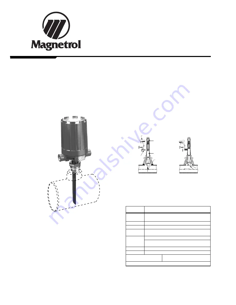
The  actuating  vane  is  magnetically  linked  to  a  pivoted 

electric  (or  pneumatic)  switch,  which  is  isolated  from  the

process by a non-magnetic barrier tube. As the actuating

vane moves with an increase in flow, it drives a magnetic

sleeve 

into the field of a permanent magnet 

located 

outside the barrier tube 

which trips the switch. As flow

decreases, the actuating vane returns to a vertical position,

allowing the magnet and switch assembly to return to the

“no Flow” position.

Switch mechanism

Adjusting screw

Magnetic sleeve

Actuating vane

Magnet

NO FLOW

POSITION

POSITION WITH 

ACTUATING FLOW PRESENT

AGENCY APPROVALS

Agency

Approval

ATEX

II

2G EEx d 

II 

C T6, explosion proof

II

1G EEx ia 

II 

C T6, intrinsically safe

CEnElEC

EEx d 

II 

C T6, explosion proof

CCE

R1 (1) 136/MI/433, explosion proof

FM

Class 

I

, Div. 1, Groups C & D

Class 

II

, Div. 1, Groups E, F & G, Type nEMA 7/9

FM/CSA

non-Hazardous area
Explosion proof area – 

Groups B, C, D, E, F & G Type nEMA 4X/7/9

SAA 

Explosion proof area

lRS

lloyds Register of Shipment (marine applications)

GOST/

Russian Authorisation Standards

GOSGORTECHnADZOR 

Other approvals are available, consult factory for more details

For CCE approved units, use the ATEX explosion proof model

numbers.

Consult factory for proper model numbers.

Summary of Contents for F10

Page 1: ...magnet and switch assembly to return to the no Flow position Switch mechanism Adjusting screw Magnetic sleeve Actuating vane Magnet NO FLOW POSITION POSITION WITH ACTUATING FLOW PRESENT AGENCY APPROVA...

Page 2: ...for trimming vane to correct length Remove 2 arrows not parallel with pipe 8 Remove F10 from pipeline 9 Check position of arrow stamped on vane support bracket This arrow should be pointing parallel w...

Page 3: ...res conductors wrap them around enclosing tube beneath the baf e plate and connect to proper terminals Check to be certain that excess wire does not interfere with tilt of switch and that adequate cle...

Page 4: ...AB BK9 BC9 BK5 BU5 BKB 1 x DPDT B8B BDB Bn9 BF9 BD5 BW5 BnB C 1 x SPDT C2B CAB CK9 CC9 C2T CAT CK5 CU5 CKB 1 x DPDT C8B CDB Cn9 CF9 C8T CDT CD5 CW5 CnB D 1 x SPDT D2B DAB DK9 DC9 DK5 DU5 DKB 1 x DPDT...

Page 5: ...nEMA 4X 10⁸ 151 257 48 4 29 5 93 10 12 1 88 nEMA 7 9 100 143 246 42 3 94 5 63 9 68 1 65 CEnElEC 110 143 249 45 4 33 5 63 9 80 1 77 Pneum sw J 110 118 216 39 4 33 4 64 8 50 1 53 Pneum sw K 130 118 216...

Page 6: ...0 Safety retainer 1 89 5912 001 89 5913 001 189 5914 001 189 5928 001 89 5929 001 189 5930 001 11 Washer 1 12 O ring 1 13 Adjustment screw 1 14 Enclosing tube 1 15 Enclosing tube gasket 1 12 1204 001...

Page 7: ...7 REPLACEMENT PARTS cont Threaded mounting Flanged mounting Serial number tage ref...

Page 8: ...actory It is mandatory that this form will be attached to each material returned This form is available through Magnetrol s local representative or by contacting the factory Please supply the followin...

Reviews: