SPARE PARTS
113
Spare Parts
Description DSD
412
Rating
Reference
Designator
Magnetek Part or
kit Number
Quantity
Per Drive
Fan
Fan
Fan
50A,100A
195A
300A
B1
B1
B1
LA05P00016-0048
LA05P00016-0012
LA05P00016-0008
1
1
1
AC Line Fuse, 50A/700V
AC Line Fuse, 70A/700V
AC Line Fuse, 150A/700V
AC Line Fuse, 250A/700V
AC Line Fuse, 400A/700V
25A
50A
100A
195A
300A
F1-F3
F1-F3
F1-F3
F1-F3
F1-F3
LA05P00017-0227
LA05P00017-0155
LA05P00017-0166
LA05P00017-0220
LA05P00017-0234
3
3
3
3
3
Armature Fuse, 70A/700V
Armature Fuse, 100A/700V
Armature Fuse, 200A/700V
Armature Fuse, 300A/700V
Armature Fuse, 500A/700V
25A
50A
100A
195A
300A
F4
F4
F4
F4
F4
LA05P00017-0155
LA05P00017-0178
LA05P00017-0179
LA05P00017-0366
LA05P00017-0235
1
1
1
1
1
SCR
SCR
SCR
SCR
SCR
25A
50A,
100A
195A
300A
Q1-Q6
Q1-Q6
Q1-Q6
Q1-Q6
Q1-Q12
LA05P00050-0409
LA05P00050-0409
LA05P00050-0410
LA05P00050-0412
LA46S03214-0010
6
6
6
6
12
Current Transducer
Current Transducer
Current Transducer
Current Transducer
Current Transducer
Thermistor Assembly
Thermostat
25A
50A
100A
195A
300A
ALL
300A
U1
U1
U1
U1
U1
RT1
S1, S2
LA05P00217-0015
LA05P00217-0014
LA05P00217-0042
LA05P00645-0018
LA05P00217-0020
46S03596-0050
46S03596-0060
1
1
1
1
1
1
2
Drive Control, main PCB
(Analog, RS232)
Drive Control PCB (RS422)
(Includes U13, 14, 39 ,40
software chips)
ALL
ALL
A1
A1
LA46S02975-9303
LA46S02975-9403
1
1
Field Interface PCB
Field SCR/Rect Module
ALL
ALL
A3
Q7
LA46S03594-0010
LA05P00050-0523
1
1
Armature Interface PCB
Armature Interface PCB
Armature Interface PCB
25A, 50A,
100A,195
A
300A
A2
A2
A2
LA46S02976-0032
LA46S02976-0032
LA46S03088-0012
1
1
1
Cube ID PCB
Cube ID PCB
Cube ID PCB
Cube ID PCB
Cube ID PCB
25A
50A
100A
195A
300A
A2J28
A2J28
A2J28
A2J28
A2J19
46S03577-1015
46S03577-1030
46S03577-1060
46S03577-1125
46S03577-1200
1
1
1
1
1
DSD 412 Power Supply
ALL
A4
LA05P00090-0293
1
Snubber PCB
Snubber PCB
Snubber PCB
Snubber PCB
Snubber PCB
25A
50A
100A
195A
300A
A5
A5
A5
A5
A5
LA46S03020-0010
LA46S03020-0020
LA46S03020-0030
LA46S03017-0010
LA46S03089-0010
1
1
1
1
1
Table, 10 Pos, Ribbon
25A
50A
100A
195A
300A
Drive Cont. A1-
J13
To
Field Interface
PCB, A3-J33
05P00034-0762
05P00034-0762
05P00034-0762
05P00034-0750
46S03396-0080
1
1
1
1
1
Summary of Contents for DSD 412
Page 1: ...DSD 412 DC Elevator Drive Technical Manual CS00407 rev 06...
Page 6: ...6...
Page 102: ...MAINTENANCE 102 Figure 24 Connector and E prom Locations...
Page 103: ...MAINTENANCE 103 Figure 25 Test Point Locations...
Page 115: ...OUTLINE DRAWING 100A 115 Figure 26 Drive Chassis Outline DSD 412 100 Amp...
Page 116: ...OUTLINE DRAWING 190A 116 Figure 27 Drive Chassis Outline DSD 412 195 Amp...
Page 117: ...OUTLINE DRAWING 300A 117 Figure 28 Drive Chasis Outline DSD 412 300 Amp...
Page 118: ...LAYOUT DRAWING 100A 118 Figure 29 Layout DSD 412 100 Amp A3 A1 A2 A2 L1 NEG GND L2 L3 POS...
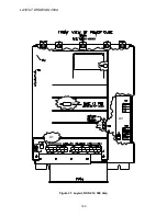
Page 119: ...LAYOUT DRAWING 195A 119 Figure 30 Layout DSD 412 195 Amp A3 A1 A2 A2...
Page 120: ...LAYOUT DRAWING 300A 120 Figure 31 Layout DSD 412 300 Amp A3 A1 A2 A2...
Page 121: ......


