MAINTENANCE
107
If the drive blows AC input fuses, check for
shorted SCRs before power is re-applied.
While the input fuses are removed for
replacement, measure circuit resistance
from each AC line to AC line on the SCR
power bridge side of the fuse connections,
and from each AC line to the DC output
busses. If resistance readings are less than
100 K-ohms, suspect shorted or badly
damaged SCRs. Replace those faulty parts
before attempting to power up again with
fresh fuses.
There is a small fuse inside the Drive Power
Supply, A4. This fuse may blow if 115 Vac
control power has surged above 135 volts.
If there is voltage at A4TB3-1 & A4TB3-7,
but the power supply does not appear to
work, this fuse may be checked by removing
the power supply cover. A blown power
supply fuse does not necessarily mean that
the power supply is faulty as the fuse also
protects a transient surge suppressor
contained within. External surges on the
115VAC control voltage power source can
cause this fuse to blow.
Testing and Replacement of Power
Semiconductors and Snubber
Components.
If SCRs are suspect, test for short circuits
before disassembly to help locate the
problem. Refer to specific instructions in
this manual for the drive ampere size.
Perform the suggested ohmmeter tests to
verify that there are no direct short circuits.
Then perform the PCU DIAGNOSTICS
#998. These tests will perform shorted and
open SCR tests to help indicate which SCRs
need replacement.
Several different DSD 412 power circuit
configurations exist in order to handle rated
currents from 25 to 1350 amperes. Refer to
the proper sub-section in this manual
according to rated drive current as listed on
the nameplate for specific service
information for the individual power
conversion units.
Testing and Replacement of the
Motor Field Control Module and PCB
Components of the DSD 412 for control of
motor field consist of the A3 PCB and
associated SCR/Rectifier module Q7 located
under the PCB. Input power is single phase
voltage supplied to A3TB1 terminals AC1
and AC2. Motor field current DC amperes
are measured by a current transducer (CT)
located on the PCB. Connecting the F1 (+)
field wire to TB4 selects the full scale current
range. Switch A3S1 is used to tell the
microprocessor what ‘tap’ is being used.
If the desired motor field current cannot be
obtained:
1. Verify that the proper AC voltage is
available at terminals A3TB1-AC1 &
A3TB1AC2. Verify that #55 is set to this
nominal value. This voltage is phase
sensitive and must be derived as shown
in drawing of Figure 2.1a.
2. Verify motor field current flow calibration
by reading motor current with a separate
clamp-on DC ammeter. Compare the
reading with that of #612. If these two
readings do not correspond, verify that
A3S1 is correctly set and that the F1(+)
lead is connected to the right tap.
3. Read and verify VDC output to the
motor field between A3TB4 F2(-) and
A).
4. Turn all power off. Temporarily remove
one power feed wire from A3TB1-AC1
and test the SCR/Rectifier module for
shorts with an ohmmeter between each
screw connection to the PCB. If short
circuits exist, replace the module AND
the PCB.
Field Control A3 PCB Replacement
1. Label and disconnect all power wires to
terminals on the PCB. Disconnect
ribbon connector J13.
2. Disconnect wires G1 & G2 from the
SCR/Rectifier module. Remove 4
screws holding PCB to SCR/Rectifier
module. Remove PCB at each plastic
post by gently pulling straight out.
3. Reverse the above procedure to
reassemble. Torque the 4
SCR/Rectifier module screws to 18 in-
lbs.
Field Control SCR/Rectifier Replacement
1. Remove the A3 PCB according to the
above.
2. Remove the 2 cap screws securing the
module to the heat-sink and remove the
damaged module.
3. Wipe the mounting surface clean. Use
a new thermal mounting pad or a thin
coating of thermal grease on the bottom
of the replacement module. Orient the
Summary of Contents for DSD 412
Page 1: ...DSD 412 DC Elevator Drive Technical Manual CS00407 rev 06...
Page 6: ...6...
Page 102: ...MAINTENANCE 102 Figure 24 Connector and E prom Locations...
Page 103: ...MAINTENANCE 103 Figure 25 Test Point Locations...
Page 115: ...OUTLINE DRAWING 100A 115 Figure 26 Drive Chassis Outline DSD 412 100 Amp...
Page 116: ...OUTLINE DRAWING 190A 116 Figure 27 Drive Chassis Outline DSD 412 195 Amp...
Page 117: ...OUTLINE DRAWING 300A 117 Figure 28 Drive Chasis Outline DSD 412 300 Amp...
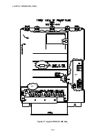
Page 118: ...LAYOUT DRAWING 100A 118 Figure 29 Layout DSD 412 100 Amp A3 A1 A2 A2 L1 NEG GND L2 L3 POS...
Page 119: ...LAYOUT DRAWING 195A 119 Figure 30 Layout DSD 412 195 Amp A3 A1 A2 A2...
Page 120: ...LAYOUT DRAWING 300A 120 Figure 31 Layout DSD 412 300 Amp A3 A1 A2 A2...
Page 121: ......


