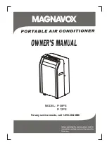
MODEL: P-08PE
P-12PE
For any service needs, call 1-855-368-8606
OWNER'S MANUAL
Page 1: ...MODEL P 08PE P 12PE For any service needs call 1 855 368 8606 OWNER S MANUAL ...
Page 2: ... by a responsible adult or considered capable enough to operate the appliance safely Children should be supervised to ensure that they do not play with the appliance If the supply cord is damaged it must be replaced by the manufacturer its service agent or similarly qualified persons in order to avoid a hazard The appliance should be installed in accordance with national wiring regulations Do not ...
Page 3: ...Control panel operating instructions 5 Operating instructions 6 Placement 8 Window kit installation 8 Exhaust hose installation 12 Water drainage 13 Care and maintenance 14 Troubleshooting tips 15 AIR CONDITIONER FEATURES CARE AND MAINTENANCE TROUBLESHOOTING TIPS OPERATING INSTRUCTIONS INSTALLATION INSTRUCTIONS PARTS IDENTIFICATION ...
Page 4: ...roperly or if it has been dropped or damaged Never use the power plug to turn unit on or off Do not cover or obstruct the inlet or outlet grilles Do not use hazardous chemicals to clean or come into contact with the unit Do not use in the presence of inflammable substances or vapor such as alcohol insecticides gasoline etc Do not allow children to operate the unit unsupervised Do not use this prod...
Page 5: ...ors and liquids in the vicinity of this or any other appliance Avoid fire hazard or electric shock Do not use an extension cord or an adaptor plug Do not remove any prong from the power cord WARNING Electrical Information PARTS IDENTIFICATION Check all the accessories are included in the package and please refer to the installation instructions for their usage NOTE Optional parts for some models o...
Page 6: ...3 4 5 Model A Model B Control Panel Horizontal Louver Blade operate manually Remote signal receptor Caster wheels Carrying Handles on each side 1 2 3 4 5 Fig 1 Fig 3 Rear 9 6 7 8 10 11 6 7 8 9 10 11 Upper Air Filter Behind the grille Air Outlet Power cord outlet Air intake Drain Outlet Air intake Lower Air Filter Behind the grille Bottom tray drain outlet 12 12 13 13 4 ...
Page 7: ... the same time for 3 seconds 3 Used to initiate the AUTO ON start time and AUTO OFF stop time program in conjuction with the buttons TIMER button 4 Used to initiate the SLEEP mode SLEEP button 6 2 Power switch on off POWER button AUTO HEAT COOL DRY FAN MODE ION SLEEP FAN TIMER ON TIMER OFF F C 5 FAN button 7 O Shows the set temperature in C or O F and the Auto timer settings While on DRY and FAN m...
Page 8: ...he temperature you have selected and thecurrent room temperature While the unit is on press the Timer button the TIMER OFF indicator light illuminates This indi cates the Auto Stop program is initiated Press or hold the UP or DOWN button to change the Auto time by h half an our increments up to 10 hours then at 1 hour increments up to 24 hours The control will count down the time remaining until s...
Page 9: ...n the louver s doing o will cause damage to the unit Ensure the louver is fully opened during heating operation Adjust the air flow direction automatically Fig 6 When the unit is turned ON the louver opens fully Use the SWING button on the remote control to adjust the louver to the desired angle O The louver moves at an angle of 6 for each press until it is at maximum angle at which point it chang...
Page 10: ...asters for easy mobility but it should only be rolled on smooth flat surfaces Use caution when rolling on carpet surfaces Do not attempt to roll the unit over objects The unit must be placed within reach of a properly grounded socket Never place any obstacles around the air inlet or outlet of the unit Allow 1 ft to 3 3 ft of space from the wall to the window for efficient air conditioning Your win...
Page 11: ...f window is less than 26 5 inches Open the window sash and place the window slider kit on the window sill See Fig 11 3 Cut the foam seal adhesive type to the proper length and attach it on the top of the window Shown as in Fig 12 4 Close the window sash securely against the window 5 Cut the foam seal to an appropriate length and seal the open gap between the top window sash and outer window sash S...
Page 12: ...if the width of window is less than 26 5 inches Open the window sash and place the window slider kit on the window sill See Fig 15 3 Cut the foam seal adhesive type to the proper length and attach it on the top of the window Shown as in Fig 16 4 Close the sliding sash securely against the window 5 Cut the foam seal to an appropriate length and seal the open gap between the top window sash and oute...
Page 13: ...nd the window sill when there is the gap between them as shown below Window kit Window sill Fig A Gap Window kit Window sill Fig A1 White foam seal Seal the white foam seal Window kit Gap Window frame or wall Fig B Window kit Window frame or wall Fig B1 Seal the white foam seal White foam seal 11 ...
Page 14: ...he previous pages for window kit installation 2 Place the Exhaust hose over against the air outlet opening hook See Fig 19 and flat the other end See Fig 20 for quick installation IMPORTANT DO NOT OVER BEND THE DUCT SEE Fig 21 Fig 18 Fig 19 Fig 20 Fig 21 Note Cover the hole using the adaptor cap when not in use Push in Hook COOL HEAT heat pump type or AUTO mode FAN DEHUMIDIFY or HEAT electrical he...
Page 15: ...er level of the bottom tray reaches a predetermined level Carefully move the unit to a drain location remove the bottom drain plug and let the water drain away Fig 24 Restart the machine and wait for the P1 symbol to disappear If the error continues call for service the unit beeps 8 times the digital display area shows P1 At this time the air conditioning dehumidification process will immediately ...
Page 16: ...ilter on the air inlet grille then install the grille by using the screw 2 Unit enclosure Use a lint free cloth soaked in neutral detergent to clean the unit enclosure Finish with a dry clean cloth Fig 25 3 Unit idle for a long time Air filter slide out Remove the rubber plug at the back of the unit and attach a hose to drain outlet Place the open end of the hose directly over a drain or separate ...
Page 17: ...y dust 2 Not cool enough Place the unit on a flat level ground if possible This is normal The ground is not level or not flat enough The sound comes from the flowing of the refrigerant inside the air conditioner Switch on again after the unit has cool down The automatic over heat protection function When the temperature at the air outlet O O exceeds 70 C 158 F the device will stop Heating mode P1 ...
Page 18: ...MAGNAVOX and SMART VERY SMART are registered trademarks of Koninklijke Philips N V and are used under license from Koninklijke Philips N V ...