background image

Removing the Protective Cover

This protective cover, on the right side of the hub, is designed to shield the unit
from potentially damaging agents that might cause this unit to malfunction or
behave erratically if the MII port is exposed. However, when a Dual-Speed Fast
Ethernet Hub cascades to another Dual-Speed Fast Ethernet Hub, this protective
cover cannot close properly. Therefore, this cover is designed with a brake-away
part to provide space for the MII cable to pass through.

1.

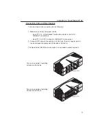
Locate the MII Port on the right side of the hub.

2.

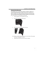
Remove the cover from the hub chassis.

3.

Fold and brake away the extra part of the cover.

Note: There is a cutter on the protective cover and it will break into two pieces

when forces are applied to the cover.

4.

Replace the protective cover back onto the hub chassis.

Installing a Dual-Speed Hub

17

Summary of Contents for FDH-608/616

Page 1: ...1 User s Manual Dynamic Dual Speed Hub FDH 608 616 R acsense...

Page 2: ...rds 7 Cables Required 7 Chapter 4 How to Configure a Fast Ethernet Network 9 Cable Length 9 Uplinking 9 Different Network Topologies 10 Other Ways to Expand a Network 11 Chapter 5 How to Install a Hub...

Page 3: ...in a routing table The information on this routing table helps to identify the traffic and directs fast 100BASE TX or slow 10BASE traffic to the proper repeater buses By separating the two repeater bu...

Page 4: ...e RJ 45 ports using Category 5 UTP UTP 5 Category 1 STP STP 1 for 100BASE TX or Category 3 4 5 UTP UTP 3 4 5 Category 1 STP STP 1 or equiva lent cables for 10BASE T We recommend starting from the high...

Page 5: ...er Switch Repeater hub Individual port status LEDs for LINK RX 10 100 PAR and 10 100 Collision status LEDs General Features of FDH 616 16 Port Dual Speed Stackable Hub Compliant with the IEEE802 3 10M...

Page 6: ...EIA designation Each jack serves to connect a cable to the network device The jack label 1X is designated as an uplink jack Uplink jacks are designed for connections to other network devices 4 8 3 7...

Page 7: ...hat s more these stackable hubs break Fast Ethernet s two hub cascade barrier allowing you to link up to three hubs via the built in stack ports using any combination of these hub models These Dual Sp...

Page 8: ...ions occur when two or more nodes accidentally attempt to transmit data across the network at the same time This happens more often with increased traf fic Naturally when you have more packets traveli...

Page 9: ...lisioned nodes to prevent further disruption of the network Showing whether each network node is currently connected and idle trans mitting data or in 10BASE T 100BASE TX mode However according to the...

Page 10: ...and Fast Ethernet Standards Standards for Ethernet and Fast Ethernet systems are issued by the Institute of Electrical and Electronic Engineers IEEE The standard for Ethernet twisted pair networks is...

Page 11: ...ed pair UTP 3 4 5 or Category 1 shielded twisted pair STP 1 or any equivalent cable to transmit data 100BASE TX requires Category 5 unshielded twisted pair UTP 5 or Category 1 shielded twisted pair ST...

Page 12: ...ion to each cable ensuring that no cable exceeds the length limit and that this length is well managed between end nodes and the hub Uplinking Uplinking a hub with another network expansion device suc...

Page 13: ...ne device or it can used in a multiple device environment Standalone device When just one hub is being used in a network the hub is said to be a stand alone hub The hub can only be connected to users...

Page 14: ...users may want to expand further improve network capabilities or integrate other networks Here is a brief introduction to the different ways of optimizing a network Dual Speed hubs Dual speed devices...

Page 15: ...utomatically adjust itself to the power available Humidity The hub and indeed the entire network should be located in the driest area possible Humid places should be avoided as humidity can damage the...

Page 16: ...led near a power outlet preferably one located in a position that is central to all network end nodes Hardware The availability of all connectors and cables required to install the hub and network sho...

Page 17: ...nnections Use UTP 5 or STP 1 cables for 100BASE TX connections 2 Connect UTP Cable to the uplink port of the Hub then to a regular port on the Dual Speed Stackable Hub FDH 608 or FDH 616 The figure be...

Page 18: ...an easily meet the networking needs of most small to medium sized workgroups As your workgroups gradually expand just add more hubs to your stack or cascade to another hub or switch using ordinary str...

Page 19: ...st Ethernet Hub this protective cover cannot close properly Therefore this cover is designed with a brake away part to provide space for the MII cable to pass through 1 Locate the MII Port on the righ...

Page 20: ...ng plugged into the end node s adapter it should be plugged into the hub s selected jack The following cable requirements should be remembered before proceeding with connections Cables must be of a UT...

Page 21: ...ll shine steadily The hub will then automatically test each port connection The end node must be turned on for the test to succeed If the end node is not turned on the port will indicate a connection...

Page 22: ...never the hub is connected to the wall adapter If the green light fails to shine steadily contact your dealer 10M COL indicator For FDH 608 FDH 616 Color Yellow Label Collision 100M COL indicator For...

Page 23: ...dicator For FDH 608 Color Green Label Link One link LED is displayed for each port on the hub This indicator shows whenever the hub is receiving information When data is reaching the hub this indicato...

Page 24: ...ed to see if it is defective Length limits Remember that the length limit for a connection between an end node and a hub cannot exceed 100 meters Cable being used for the connection Straight through c...

Page 25: ...sure that all cables from node to node do not exceed the recom mended maximum length of 100 meters Checking the quality of the cables and outlets used to connect the hub to end nodes and to the wall a...

Page 26: ...104 F Storage 25 C to 70 C 13 F to 158 F Humidity 5 to 95 non condensing Net Weight 900g 1 98lbs FDH 616 Standards IEEE 802 3 10BASE T IEEE 802 3u 100BASE TX Ports 16 x 10BASE T 100BASE TX ports and...

Page 27: ...ticular installation If this equipment does cause harmful interference to radio or television reception which can be determined by turning the equipment off and on the user is encouraged to try to cor...

Reviews: