262391
111
Revision A
1011305
B
A
C
D
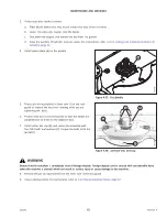
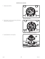
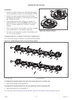
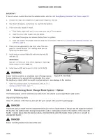
Figure 4.58: Cutterbar Disc and Cap
14. Place a pin (or equivalent) in front hole (D) of the rock
guard to prevent the disc from rotating while you are
tightening the bolts.
IMPORTANT:
The blades are oriented to cut in one direction or the other.
Therefore, swap the entire disc when swapping spindles.
15. Position disc (A) on the spindle, ensuring that it is
positioned at a 90° angle relative to the adjacent discs.
NOTE:
Turn disc (A) by hand to ensure that the disc blades do not
contact each other or adjacent discs.
16. Install cutter disc cap (B) and secure the assembly with four
M12 bolts and washers (C). Torque the bolts to 85 Nm
(63 lbf·ft).
WARNING
Ensure that the cutterbar is completely clear of foreign objects. Foreign objects can be ejected with considerable force
when the machine is started, which can result in serious injury or cause damage to the machine.
17. Remove the pin (or equivalent) from the front hole of the
rock guard.
18. Close the cutterbar doors. For instructions, refer to
3.4.2 Closing Cutterbar Doors, page 27
4.4.6
Reconfiguring Cutterbar Crop Stream
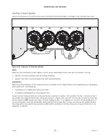
Discs are factory-installed to produce three crop streams; however, the disc rotation pattern can be changed by changing
the spindle and its disc to suit crop conditions. Each spindle and disc pair is designed to rotate in one direction, and must
be changed as a set when the crop flow is altered.
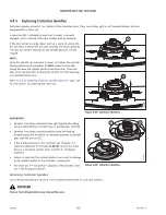
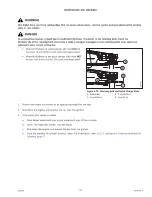
1011125
Figure 4.59: Cutterbars
Reducing or increasing the number of crop streams will produce
the following results:
•
Reducing the number of crop streams will result in narrower
windrows.
•
Increasing the number of crop streams will result in
smoother, wider windrows.
NOTE:
Increasing the number of crop streams will also increase the
number of diverging disc pairs. This may negatively affect
the quality of the cutting.

