background image

215505

25

Revision A

Chapter 5:

Installation Instructions

To install the kits, follow all procedures in the order provided.

5.1

Installing Bushings and Steel Fingers to Reels

$

%

&

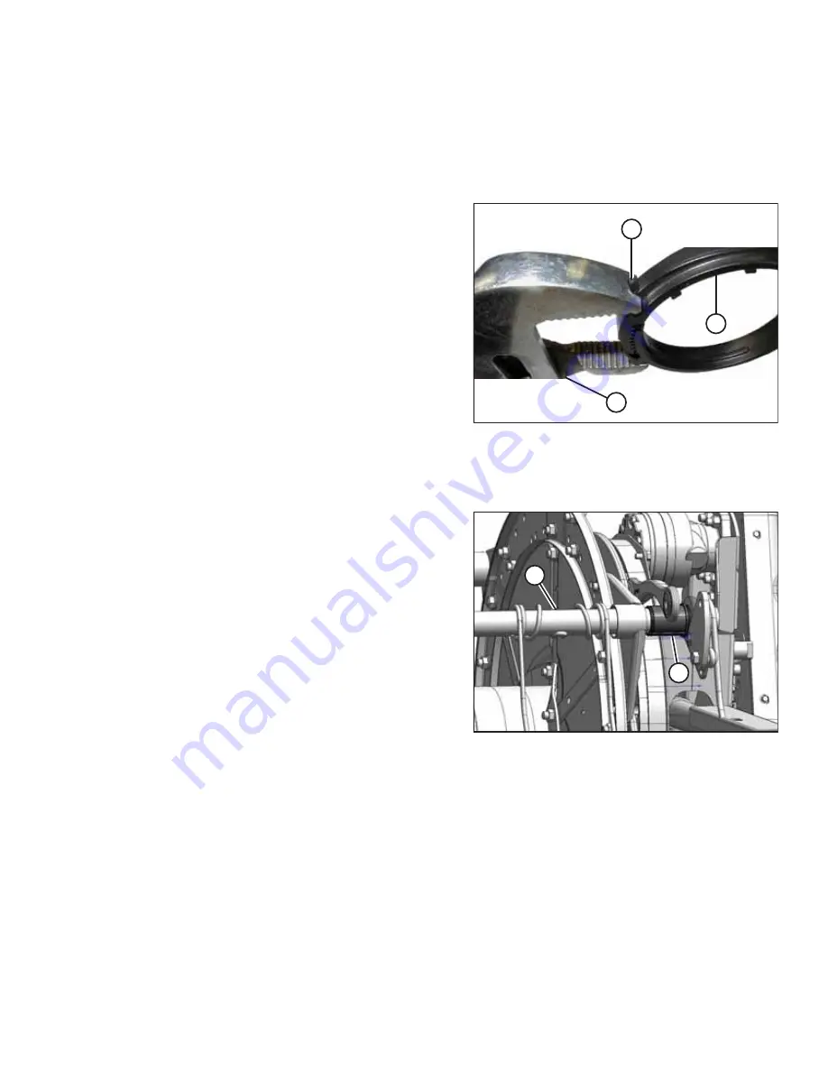
Figure 5.1: Modified Channel Lock Pliers

Use a pair of modified channel lock pliers (A) to install bushing
clamps (C). Secure pliers in a vise and grind a notch (B) into the
end of each arm to fit the clamp as shown.

1.

Support the tine tube at all times to prevent damage to the tube or other components.

Cam end bushings

$

%

Figure 5.2: Cam End

2.

Position bushing halves (B) on tine tube (A) with the
flangeless end adjacent to the tine tube arm, and position
the lug in each bushing half into the hole in the tine tube.

3.

Slide tine tube (A) towards the tail end of the reel to insert
bushing (B) into the tine tube arm. If the tine tube supports
are installed, ensure the bushings at those locations slide
into the support.

Summary of Contents for FlexDraper FD2 Series

Page 1: ...lexDraper Header for Combines Steel Finger Kits MD 311054 311055 311068 and 311069 Installation Instructions 215505 Revision A Original Instruction Featuring MacDon FLEX FLOAT Technology The Harvesting Specialists ...

Page 2: ...n is based on the information available and in effect at the time of printing MacDon Industries Ltd makes no representation or warranty of any kind whether expressed or implied with respect to the information in this publication MacDon Industries Ltd reserves the right to make changes at any time without notice ...

Page 3: ...t is approximately 3 hours Conventions The following conventions are used in this document Right and left are determined from the operator s position The front of the header is the side that faces the crop the back of the header is the side that connects to the combine Unless otherwise noted use the standard torque values provided in the header operator s manual and technical manual NOTE This docu...

Page 4: ......

Page 5: ...rrow 10 3 2 FD230 Double Reel Five and Six Bats Wide 11 3 3 FD235 Double Reel Five and Six Bats Narrow 12 3 4 FD235 Double Reel Five and Six Bats Wide 13 Chapter 4 Removing Existing Fingers and Bushings 15 4 1 Removing Bushings and Steel or Plastic Fingers from Reels 15 Chapter 5 Installation Instructions 25 5 1 Installing Bushings and Steel Fingers to Reels 25 5 2 Installing Reel Endshields 33 5 ...

Page 6: ......

Page 7: ...idelines DANGER Indicates an imminently hazardous situation that if not avoided will result in death or serious injury WARNING Indicates a potentially hazardous situation that if not avoided could result in death or serious injury It may also be used to alert against unsafe practices CAUTION Indicates a potentially hazardous situation that if not avoided may result in minor or moderate injury It m...

Page 8: ...es Heavy gloves Wet weather gear Respirator or filter mask Figure 1 2 Safety Equipment In addition take the following precautions Be aware that exposure to loud noises can cause hearing impairment or loss Wear suitable hearing protection devices such as earmuffs or earplugs to help protect against loud noises Figure 1 3 Safety Equipment Provide a first aid kit in case of emergencies Keep a properl...

Page 9: ...hine function and or safety It may also shorten the machine s life To avoid injury or death from unexpected startup of the machine ALWAYS stop the engine and remove the key from the ignition before leaving the operator s seat for any reason Figure 1 6 Safety around Equipment Keep service area clean and dry Wet and or oily floors are slippery Wet spots can be dangerous when working with electrical ...

Page 10: ......

Page 11: ...11324 FINGER LH SINGLE CONCENTRIC 10 2 311323 FINGER RH SINGLE CONCENTRIC 4 3 311322 FINGER TAIL END INBOARD 5 4 311321 FINGER TAIL END OUTBOARD 5 5 137092 FINGER 135 6 220941 CLAMP TINE TUBE BUSHING CENTER RIB BOX OF 5 6 7 273052 RETAINER END FINGER 10 A 108172 BOLT HEX HD M10 X 1 5 X 65 8 8 AA1J 10 B 184584 WASHER CON SPRING M10 STL SAE 10 C 135800 NUT HEX CTR LOC SPCL M10 X 1 5 9 AA1J 10 D 1371...

Page 12: ...NGER TAIL END INBOARD 6 4 311321 FINGER TAIL END OUTBOARD 6 5 137092 FINGER 135 6 220941 CLAMP TINE TUBE BUSHING CENTER RIB BOX OF 5 8 7 273052 RETAINER END FINGER 12 A 108172 BOLT HEX HD M10 X 1 5 X 65 8 8 AA1J 12 B 184584 WASHER CON SPRING M10 STL SAE 12 C 135800 NUT HEX CTR LOC SPCL M10 X 1 5 9 AA1J 12 D 137118 BOLT BTN HD RIB NK 3 8 NC 153 E 30228 NUT FLG DT SM FACE 3 8 16 UNC GR5 AA1J 153 PAR...

Page 13: ...INGER TAIL END INBOARD 5 4 311321 FINGER TAIL END OUTBOARD 5 5 137092 FINGER 143 6 220941 CLAMP TINE TUBE BUSHING CENTER RIB BOX OF 5 8 7 273052 RETAINER END FINGER 10 A 108172 BOLT HEX HD M10 X 1 5 X 65 8 8 AA1J 10 B 184584 WASHER CON SPRING M10 STL SAE 10 C 135800 NUT HEX CTR LOC SPCL M10 X 1 5 9 AA1J 10 D 137118 BOLT BTN HD RIB NK 3 8 NC 191 E 30228 NUT FLG DT SM FACE 3 8 16 UNC GR5 AA1J 191 PA...

Page 14: ...NGER TAIL END INBOARD 6 4 311321 FINGER TAIL END OUTBOARD 6 5 137092 FINGER 171 6 220941 CLAMP TINE TUBE BUSHING CENTER RIB BOX OF 5 10 7 273052 RETAINER END FINGER 12 A 108172 BOLT HEX HD M10 X 1 5 X 65 8 8 AA1J 12 B 184584 WASHER CON SPRING M10 STL SAE 12 C 135800 NUT HEX CTR LOC SPCL M10 X 1 5 9 AA1J 12 D 137118 BOLT BTN HD RIB NK 3 8 NC 231 E 30228 NUT FLG DT SM FACE 3 8 16 UNC GR5 AA1J 231 PA...

Page 15: ...tion process to make sure the fingers are placed in the correct locations for your application 3 1 FD230 Double Reel Five and Six Bats Narrow page 10 3 2 FD230 Double Reel Five and Six Bats Wide page 11 3 3 FD235 Double Reel Five and Six Bats Narrow page 12 3 4 FD235 Double Reel Five and Six Bats Wide page 13 ...

Page 16: ...ive and Six Bats Narrow Figure 3 1 Left Side Narrow 1 MD 137092 2 MD 311321 3 MD 220941 4 MD 273052 A MD 108172 B MD 184584 C MD 135800 D MD 137118 E MD 30228 Figure 3 2 Right Side Narrow 1 MD 137092 2 MD 311324 3 MD 220941 A MD 137118 B MD 30228 ...

Page 17: ... Figure 3 3 Left Side Wide 1 MD 137092 2 MD 311321 3 MD 311323 4 MD 220941 5 MD 273052 A MD 108172 B MD 184584 C MD 135800 D MD 137118 E MD 30228 Figure 3 4 Right Side Wide 1 MD 137092 2 MD 311324 3 MD 311323 4 MD 220941 A MD 137118 B MD 30228 STEEL FINGER PLACEMENT ...

Page 18: ... 3 5 Left Side Narrow 1 MD 137092 2 MD 311321 3 MD 311324 4 MD 311323 5 MD 220941 6 MD 273052 A MD 108172 B MD 184584 C MD 135800 D MD 137118 E MD 30228 Figure 3 6 Right Side Narrow 1 MD 137092 2 MD 311324 3 MD 311323 4 MD 220941 A MD 137118 B MD 30228 STEEL FINGER PLACEMENT ...

Page 19: ...e 3 7 Left Side Wide 1 MD 137092 2 MD 311321 3 MD 311324 4 MD 311323 5 MD 220941 6 MD 273052 A MD 108172 B MD 184584 C MD 135800 D MD 137118 E MD 30228 Figure 3 8 Right Side Wide 1 MD 137092 2 MD 311324 3 MD 311323 4 MD 220941 A MD 137118 B MD 30228 STEEL FINGER PLACEMENT ...

Page 20: ......

Page 21: ...aised reel always engage reel safety props before going under raised reel for any reason IMPORTANT Ensure the tine tube is supported at all times to prevent damage to the tube and other components 1 Lower the header fully 2 Raise the reel fully 3 Shut down the engine and remove the key from the ignition 4 Engage the reel safety props For instructions refer to the FD2 FM200 Operators Manual Center ...

Page 22: ...rd off of bushing B 9 Remove bushing halves B If required remove the next steel or plastic finger so the arm can slide off the bushing Refer to the following steps as necessary for removing steel or plastic fingers Figure 4 4 Removing Steel Finger Steel Finger 10 Remove bolts B from the existing fingers and slide the fingers over the tine tube to remove remove tine tube arms A from the tine tubes ...

Page 23: ...e clip at the top of the finger back towards the reel tube as shown and remove the finger from the tube Cam end bushings Figure 4 7 Cam End 13 Remove the endshields and endshield support A at the applicable tine tube location on the cam end NOTE Removing cam end bushings requires the tine tube to be moved through the disc arms to expose the bushing REMOVING EXISTING FINGERS AND BUSHINGS ...

Page 24: ...einforcing kit option 1 Figure 4 9 Tine Tube Supports 16 Release the bushing clamps or disconnect the support channels from the tine tube support if installed depending on which tine tube is being moved Three tine tubes A require channel disconnection and two tine tubes B require only bushing clamp removal Figure 4 10 Cam End 17 Remove bolt C and washer D from the cam arm B so tine tube A is free ...

Page 25: ...shing B 20 Remove bushing halves B If required remove the next steel or plastic finger so the arm can slide off the bushing Refer to the following steps as necessary for removing steel or plastic fingers Figure 4 13 Removing Steel Finger Steel Finger 21 Remove bolts B from the existing fingers and slide the fingers over the tine tube to remove remove tine tube arms A from the tine tubes as necessa...

Page 26: ...ube as shown and remove the finger from the tube Tine tube reinforcing kit bushings option Figure 4 16 Tine Tube Support 24 Locate support A that requires a new bushing 25 Remove four bolts B securing channel C to support A 26 Remove screw E and remove finger D if it is too close to the support to allow access to the bushing Refer to the following steps as necessary for removing steel or plastic f...

Page 27: ...emove tine tube arms A from the tine tubes as necessary Figure 4 18 Removing Plastic Finger Plastic Finger 28 Remove screw A using a Torx Plus 27 IP socket wrench Figure 4 19 Removing Plastic Finger Plastic Finger 29 Push the clip at the top of the finger back towards the reel tube as shown and remove the finger from the tube REMOVING EXISTING FINGERS AND BUSHINGS ...

Page 28: ... separate the serrations Figure 4 21 Tine Tube Reinforcing Kit Bushing Clamp Option 31 Move clamps A off the bushings Figure 4 22 Tine Tube Reinforcing Kit Support Option 32 On each reel there are three right facing supports A Slide the support off bushing halves B REMOVING EXISTING FINGERS AND BUSHINGS ...

Page 29: ... 33 On each reel there are two left facing supports A Rotate the supports until the flanges clear the channels before moving them off bushing B Move the tube slightly away from the reel if necessary 34 Remove bushing halves B from the tine tubes REMOVING EXISTING FINGERS AND BUSHINGS ...

Page 30: ......

Page 31: ...the end of each arm to fit the clamp as shown 1 Support the tine tube at all times to prevent damage to the tube or other components Cam end bushings Figure 5 2 Cam End 2 Position bushing halves B on tine tube A with the flangeless end adjacent to the tine tube arm and position the lug in each bushing half into the hole in the tine tube 3 Slide tine tube A towards the tail end of the reel to inser...

Page 32: ... Install bushing clamp A onto the tine tube adjacent to the flangeless end of bushing B 8 Position clamp A on bushing B so the edges of the clamp and bushing are flush when the clamp is fit into the groove on the bushing and the lock tabs are engaged NOTE Clamp is not symmetrical inner flange needs to be to the outside Figure 5 5 Installing Clamp 9 Tighten clamp A using modified channel lock plier...

Page 33: ...m arm Figure 5 7 Tail End 11 Install bolts A securing tine tube arm B to the center disc 12 Install tine tube arm B and endshield support C to the tail end of the reel at the applicable tine tube location and secure with bolts A NOTE There are no endshields on the center discs Figure 5 8 Cam End 13 Install endshield support A at the applicable tine tube location at the cam end INSTALLATION INSTRUC...

Page 34: ...m A onto the end of the tube 17 Attach the fingers to the tine tube with bolts and nuts B For finger location and proper hardware installation refer to 3 Steel Finger Placement page 9 18 Torque steel finger hardware to 35 Nm 26 lbf ft NOTE Do NOT overtighten hardware may result in flattening of tube Figure 5 11 Bushing 19 Install bushing clamp A onto the tine tube adjacent to the flangeless end of...

Page 35: ...c 23 Install tine tube arm B and endshield support C to the tail end of the reel at the applicable tine tube location and secure with bolts A NOTE There are no endshields on the center discs Tine tube reinforcing kit option 2 Figure 5 14 Cam End 24 Position bushing halves B on tine tube A with the flangeless end adjacent to the tine tube arm and position the lug in each bushing half into the hole ...

Page 36: ...ntil its flanges clear channels C before moving the support onto bushing B NOTE If necessary move tine tube D slightly away from the reel to allow the support flange enough room to clear the channel Figure 5 17 Bushing 27 Install bushing clamp A onto the tine tube adjacent to the flangeless end of bushing B 28 Position clamp A on bushing B so the edges of the clamp and bushing are flush when the c...

Page 37: ...e three right facing supports A on each reel with screws B and nuts Torque screws to 43 Nm 32 lbf ft Figure 5 20 Tine Tube 31 Slide the new finger and tine tube arm A onto the end of the tube 32 Attach the fingers to the tine tube with bolts and nuts B For finger location and proper hardware installation refer to 3 Steel Finger Placement page 9 33 Torque steel finger hardware to 35 Nm 26 lbf ft NO...

Page 38: ...er and tine tube arm A onto the end of the tube 36 Attach the fingers to the tine tube with bolts and nuts B For finger location and proper hardware installation refer to 3 Steel Finger Placement page 9 37 Torque steel finger hardware to 35 Nm 26 lbf ft NOTE Do NOT overtighten hardware may result in flattening of tube 38 Continue onto installing endshields For instructions refer to 5 2 Installing ...

Page 39: ...you are reinstalling the endshields in the correct locations as shown below NOTE The arrow points to the front of the machine Figure 5 23 Reel Endshields A Tail End Outboard MD 311695 B Cam End Inboard MD 273823 C Tail End Inboard MD 311795 D Cam End Outboard MD 311694 INSTALLATION INSTRUCTIONS ...

Page 40: ...stall the cam end outboard endshield A follow these steps NOTE The endshield segments used for this procedure have two additional holes B on one end Do NOT confuse them with the segments C used for the outboard tail end of the reel NOTE The arrow points to the front of the machine Figure 5 24 Five Bat Reel Endshield Cam End Outboard INSTALLATION INSTRUCTIONS ...

Page 41: ... follows a Position endshield segment A BEHIND segment B Engage endshield support tabs C through both segments and secure with M10 X 1 5 X 20 Torx screw D and hex nut E Do NOT tighten b Repeat for the remaining segments leaving last segment F and two support tabs G uninstalled INSTALLATION INSTRUCTIONS ...

Page 42: ...ree RUBBER reel end paddles A on the OUTBOARD FACE of the endshield assembly using two M8 X 1 25 X 20 hex bolts B and nuts C per paddle 3 If removed install four ALUMINUM cam deflectors D on the INBOARD FACE of the endshield assembly shown using two M10 X 1 5 X 16 Torx screws E and hex nuts F 4 Install ALUMINUM cam deflector G on the last segment as shown using two M10 X 1 5 X 16 Torx screws and h...

Page 43: ...tially Assembled Reel Endshields on Reel NOTE The arrow points to the front of the machine 5 Position the partially assembled reel endshield onto the reel 6 Secure with three M12 X 1 75 X 30 hex bolts A and nuts Do NOT tighten INSTALLATION INSTRUCTIONS ...

Page 44: ...ure endshield supports using two M10 X 1 5 X 20 Torx screws E and nuts F d Torque five M10 X 1 5 X 20 Torx screws E and G to 39 Nm 29 lbf ft Rotate the reel to reach the screws if required 8 Slip the endshield supports onto tine tubes H NOTE Not all tine tubes shown in illustration 9 Secure the two endshield supports to the reel disc using two M12 X 1 75 X 30 hex bolts J and nuts 10 Tighten five M...

Page 45: ...ng Reel Endshields at Inboard Tail End This procedure is applicable to the inboard tail end on all reel configurations To install the tail end inboard endshield A follow these steps Figure 5 29 Inboard Tail End INSTALLATION INSTRUCTIONS ...

Page 46: ... into endshield segment B b Place the cupped end of endshield segment C ON TOP of segment B Attach the segments using two with M10 X 1 5 X 16 Torx screws D and nuts E Do NOT tighten the hardware c Repeat for the remaining segments leaving last segment F and two bushings G uninstalled INSTALLATION INSTRUCTIONS ...

Page 47: ...l as follows a Insert three bushings A into the tine tubes Align the bushing hole B and finger slot with the hole in the tine tube C b Secure the bushings and fingers to the tine tube using bolt D and nut E Do NOT tighten NOTE The arrow points to the front of the machine INSTALLATION INSTRUCTIONS ...

Page 48: ...ment c Insert bushing E end of segment into the tine tube Secure the bushing and finger to the tine tube using bolt F and nut G Do NOT tighten d Place cupped end of segment H ON TOP of segment A e Secure the endshield segments with M10 X 1 5 X 16 Torx screws J and nuts K 4 Prevent the flattening of the tubes Torque all the tine tube steel finger bolts and nuts to 9 Nm 7 lbf ft Do NOT overtighten t...

Page 49: ...dshields at Inboard Cam End This procedure is applicable to the inboard cam end on all reel configurations To install the cam end inboard endshield A follow these steps Figure 5 33 Five Bat Reel Endshield Cam End Inboard INSTALLATION INSTRUCTIONS ...

Page 50: ... follows a Position endshield segment A BEHIND segment B Engage endshield support tabs C through both segments and secure with M10 X 1 5 X 20 Torx screw D and hex nut E Do NOT tighten b Repeat for the remaining segments leaving last segment F and two support tabs G uninstalled INSTALLATION INSTRUCTIONS ...

Page 51: ... deflectors are oriented as shown 2 If removed install four ALUMINUM cam deflectors A on the INBOARD FACE of the endshield assembly shown using two M10 X 1 5 X 16 Torx screws B and hex nuts C 3 If removed install ALUMINUM cam deflector D on the last segment as shown using two M10 X 1 5 X 16 Torx screws and hex nuts INSTALLATION INSTRUCTIONS ...

Page 52: ...tially Assembled Reel Endshields on Reel 4 Position the partially assembled reel endshield onto the reel NOTE The arrow points to the front of the machine 5 Secure with three M12 X 1 75 X 30 hex bolts A and nuts Do NOT tighten INSTALLATION INSTRUCTIONS ...

Page 53: ...ld segments c Secure the endshield supports using two M10 X 1 5 X 20 Torx screws E and nuts F d Torque five M10 X 1 5 X 20 Torx screws E and G to 39 Nm 29 lbf ft Rotate the reel to reach the screws if required 7 Slip the endshield supports onto tine tubes H NOTE Not all tine tubes are shown in illustration 8 Secure the two endshield supports to the reel disc using two M12 X 1 75 X 30 hex bolts J a...

Page 54: ...elds at Outboard Tail End This procedure is applicable to the outboard tail end on all reel configurations To install the tail end outboard endshield A follow these steps Figure 5 38 Five Bat Reel Endshield Outboard Tail End INSTALLATION INSTRUCTIONS ...

Page 55: ...ints to the front of the machine a Position endshield segment A IN FRONT of segment B Engage endshield support tabs C through both segments and secure with M10 X 1 5 X 20 Torx screw D and hex nut E Do NOT tighten b Repeat for remaining segments leaving last segment H and two support tabs G uninstalled INSTALLATION INSTRUCTIONS ...

Page 56: ...BOARD FACE of the endshield assembly using two M8 X 1 25 X 20 hex bolts B and nuts C per paddle IMPORTANT The arrow points to the front of the machine Ensure the rubber paddles are oriented as shown The rubber paddles on both ends of the reel the outboard cam and outboard tail ends should be aligned INSTALLATION INSTRUCTIONS ...

Page 57: ...ssembled Reel Endshields on Reel 3 Position the partially assembled reel endshield onto the reel and tine tubes NOTE The arrow points to the front of the machine 4 Secure with three M12 X 1 75 X 30 hex bolts A and nuts Do NOT tighten INSTALLATION INSTRUCTIONS ...

Page 58: ...l the tabs of endshield supports D through the endshield segments c Secure the endshield supports using two M10 X 1 5 X 20 Torx screws E and nuts F d Torque five M10 X 1 5 X 20 Torx screws E and G to 39 Nm 29 lbf ft Rotate the reel to reach the screws if required 6 Secure the two endshield supports to the reel disc using two M12 X 1 75 X 30 hex bolts H and nuts 7 Tighten five M12 X 1 75 X 30 hex b...

Page 59: ......

Page 60: ...3 f 816 891 7323 LLC MacDon Russia Ltd 123317 Moscow Russia 10 Presnenskaya nab Block C Floor 5 Office No 534 Regus Business Centre t 7 495 775 6971 f 7 495 967 7600 MacDon Australia Pty Ltd A C N 079 393 721 54 National Boulevard Campbellfield Victoria Australia 3061 t 61 3 8301 1911 f 61 3 8301 1912 MacDon Europe GmbH Edisonstrasse 63 Haus A 12459 Berlin Germany t 49 30 408 172 839 CUSTOMERS Mac...

Reviews: