


03
t +31 88 500 2800
www.maaslandgroep.nl
VERGRENDELINGEN
DEURDRANGERS
ACCESSOIRES
TOEGANGSCONTROLE
ELEKTROMAGNETEN
DEURBESLAG
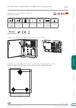
NETVOEDINGEN / POWER SUPPLIES / ALIMENTATION / SCHALTNETZTEIL
PS1215
080121
GENERAL INFORMATION
• These power supplies are intended for installation by qualified persons only.
• There are no user serviceable parts in the power supply, therefor no regular maintenance is required other than
ensuring all cables are securely fixed and free from damage.
• Batteries should be tested periodically with appropriate measuring equipment. Consult the manufacturer of the
respective battery for specifications.
• The tamper contacts are voltage free and should not be used for any other purpose.
There is a risk of explosion if the battery is replaced by the wrong type of battery. Only use a sealed
lead acid batteries. Dispose of batteries in accordance with the regulations for the disposal of
batteries.
INSTALLATION INSTRUCTIONS
Only suitable as fixed installation, parts mentioned in the manual cannot be mounted outdoors.
1.
Mount the power supply on a flat surface with the box hinges on the left side. The power supply must be
mounted in a location where airflow is possible, avoid locations with high humidity or high temperatures.
2.
Connect the power supply to a grounded outlet with a suitable mains voltage and installed by a certified
electrician.
This product must be earthed.
3 .
Connect the equipment and any other necessary connections. The 12V or 13.8V output is marked with + OUT -.
The cable thickness must be determined according to the consumption of the connected devices.
The TAMPER contact is NO or NC (Normally Open or Normally Closed) and is only intended for connecting a
suitable alarm system. Normally Open contact when lid is opened and Normally Close contact when the lid is
closed. Connect battery if applicable. The output is marked with + BATT -. Red + and black -.
4.
It is recommended not to route the mains cable and low voltage cables together. When cables are routed
through the entry/exit holes in the metal housing, glands must be used. It is recommended to secure all cables
in the metal housing with cable ties.
5.
Connect the mains voltage and switch it on. Check if the green LED is lit.
6.
Check that the ground wire is connected to the metal housing and the lid of the metal housing.
7.
Close lid and secure with screw provided.
The battery reset is for when the 230V is no longer available due to a fault and the connected
battery is empty and a new battery must be installed to supply voltage on the 12V output. In
this situation, connect the new battery but not the 230V. Press and hold SW1 for 3
seconds. The battery will supply power to the output.
!
!
SW1
!