5-2-55, Minamitsumori, Nishinari-ku, Osaka 557-0063 JAPAN
Phone: +81(6)6659-8201 Fax: +81(6)6659-8510 E-mail: [email protected]
EM-8121 Rev.9 P. 1 / 3
INSTRUCTION MANUAL
LIGHTNING SURGE PROTECTOR FOR
AC/DC POWER SUPPLY USE (1A)
MODEL
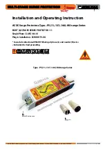
MDP-100
MDP-200
BEFORE USE ....
Thank you for choosing M-System. Before use, please check
contents of the package you received as outlined below.
If you have any problems or questions with the product,
please contact M-System’s Sales Office or representatives.
■
PACKAGE INCLUDES:
Surge protector ....................................................................(1)
DIN rail mounting adaptor* ...............................................(1)
Screws for DIN rail mounting (M4 × 8)* ...........................(2)
*Included with option code /A33
■
MODEL NO.
Confirm Model No. marking on the product to be exactly
what you ordered.
■
INSTRUCTION MANUAL
This manual describes necessary points of caution when
you use this product, including installation, connection and
basic maintenance procedures.
LIMITATION APPLICABLE TO M-RESTER
The M-RESTER will protect electronics equipment from
damage caused by lightning by absorbing most of the
surge voltages.
However, M-RESTER may not be effective against cer-
tain extremely high voltages caused by a direct or almost
direct hit by lightning.
M-RESTER must be installed according to this installa-
tion / instruction manual.
GENERAL
■
FUNCTION & FEATURES
• Designed for AC and specifically for DC power supplies
up to 1A
• Beneficial for protecting instruments from counter elec-
tromotive force by inductors and of course normal light-
ning surges entering from power supply lines
• 1A fuse incorporated in element circuit
■
SPECIFICATIONS
LINE TO LINE
LINE TO
EARTH
MDP-100
MDP-200
Max. line voltage (Uc)
120V AC
170V DC
250V AC
355V DC
----
Discharge voltage
190V
410V
410V
Voltage protection level (Up)
400V
800V
800V
Leakage current
≤ 0.1mA
@150V DC
≤ 0.1mA
@300V DC
≤ 0.1mA
@300V DC
Response time
≤ 0.1 microsecond.
Max. discharge current (Imax)
1000A (8 / 20 µs)
Nominal current (IN)
1.0A
Internal series resistance
≤ 0.4 Ω including return
Dielectric strength of the
base module
1500V AC @1 minute
(G terminal to other terminals)
POINTS OF CAUTION
■
ENVIRONMENT
• When heavy dust or metal particles are present in the
air, install the surge protector inside proper housing with
sufficient ventilation.
• Do not install the surge protector where it is subjected to
continuous vibration. Do not subject the unit to physical
impact.
• Environmental temperature must be within -5 to +60°C
(23 to 140°F) with relative humidity within 30 to 90% RH
in order to ensure adequate life span and operation.
■
DIELECTRIC STRENGTH TEST
• Loosen the screw located at the left-center of the element
and remove the element module from the base before
conducting a dielectric strength testing. Otherwise the
element will start discharging at a voltage exceeding the
max. continuous operating voltage (Uc), which can cause
insulation failure of the module.
Be sure to return the element and fasten securely after
the test.
■
AND ....
• We recommend that you keep spare surge protectors so
that you can replace them when necessary.
• Lightning surge can enter not only through power supply
lines but also through signal lines. We recommend that
you also use the surge protectors for signal line for suffi-
cient protection.
COMPONENT IDENTIFICATION
M•RESTER
Ground Terminal (G)
(used as mounting bracket)
Head Element
Base
Specifications
Head Element is secured to Base
with screw when the surge protector
is shipped from Factory.