BEFORE USE ....
Thank you for choosing M-System. Before use, please check
contents of the package you received as outlined below.
If you have any problems or questions with the product,
please contact M-System’s Sales Office or representatives.
■
PACKAGE INCLUDES:
Lightning surge protector (body + base socket) .................(1)
■
MODEL NO.
Confirm Model No. marking on the product to be exactly
what you ordered.
■
INSTALLATION / INSTRUCTION MANUAL
This manual describes necessary points of caution when
you use this product, including installation, connection and
basic maintenance procedures.
LIMITATION APPLICABLE TO M-RESTER
The M-Rester will protect electronics equipment from
damage caused by lightning by absorbing most of the
surge voltages.
However, M-Rester may not be effective against certain
extremely high voltages caused by a direct or almost di-
rect hit by lightning.
M-Rester must be installed according to this installa-
tion/ instruction manual.
GENERAL
■
FUNCTION & FEATURES
• Designed specifically to protect telecommunication equip-
ment from lightning surges entering through telecommu-
nication line network
■
SPECIFICATIONS
Btwn Lines
Line to Gnd
Discharge voltage
±190V min.
±180V min.
Max. surge voltage*
±500V max.
±900V max.
Leakage current
≤100µA
@±160V DC
≤100µA
@±160V DC
Response time
≤0.01 µsec
Discharge current capacity
Modular jack connection
Screw terminal connection
500A (8 / 20 µsec.)
10000A (8 / 20 µsec.)
Max. load current
200mA
Internal series resistance
Approx. ≤4Ω including return
Frequency band
Approx. 100 kHz/-3 dB
at 600Ω terminating resistance
Max. line voltage
±160V DC
*The maximum voltage that could pass through M-RESTER.
Protected equipment must be able to withstand this voltage
for a very short time period.
POINTS OF CAUTION
■
POWER INPUT RATINGS
• Power input ratings are specified by the model number
suffix code. Check the power input voltage for the unit on
the specification label.
AC power
: 85 – 264V, 47 – 66 Hz, approx. 2 – 4VA
DC power
: 24V ±10% or 85 – 150V, approx. 1.5W
■
UNPLUGGING THE UNIT
• Before you remove the unit from its base socket or mount
it, turn off the power supply and the signal for safety.
■
ENVIRONMENT
• Indoor use
• When heavy dust or metal particles are present in the
air, install the unit inside proper housing and ventilate it.
• Do not install the unit where it is subjected to continuous
vibration. Do not apply physical impact to the unit.
• Environmental temperature must be within -5 to +55°C
(23 to 131°F) with relative humidity within 30 to 90% RH
in order to ensure adequate life span and operation.
• Be sure that the ventilation slits are not covered with ca-
bles, etc.
■
WIRING
• Do not install cables (power supply, input and output)
close to noise sources (relay drive cable, high frequency
line, etc.).
• Do not bind these cables together with those in which
noises are present. Do not install them in the same duct.
■
AND ....
• The unit is designed to function as soon as power is sup-
plied, however, a warm up for 10 minutes is required for
satisfying complete performance described in the data
sheet.
COMPONENT IDENTIFICATION
LINE
MODEM
Body
Base Socket
Specification Label
Connection Diagram
Label (side)
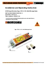
LIGHTNING SURGE PROTECTOR FOR
ANALOG TELECOM LINE USE (life monitor)
MODEL
MDA-TL
5-2-55, Minamitsumori, Nishinari-ku, Osaka 557-0063 JAPAN
Phone: +81(6)6659-8201 Fax: +81(6)6659-8510 E-mail: [email protected]
EM-8205 Rev.1 P. 1 / 3
INSTRUCTION MANUAL