EM-8283-A Rev.4 P. 1 / 6
INSTRUCTION MANUAL
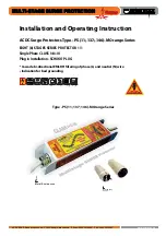
LIGHTNING SURGE PROTECTOR FOR STANDARD
SIGNAL LINE & PULSE USE
(conduit mount, weather-proof)
MODEL
MD6x-24
MD6x-65
BEFORE USE ....
Thank you for choosing M-System. Before use, please check
the contents of the package you received as outlined below.
If you have any problems or questions with the product,
please contact M-System’s Sales Office or representatives.
■
PACKAGE INCLUDES:
Lightning surge protector ...................................................(1)
■
MODEL NO.
Confirm Model No. marking on the product to be exactly
what you ordered.
■
INSTRUCTION MANUAL
This manual describes necessary points of caution when
you use this product, including installation, connection and
basic maintenance procedures.
When using this product in potentially explosive atmos-
phere or hazardous (classified) location, you have to follow
the safety procedure to install it. Please refer to “SAFE IN-
STALLATION MANUAL” for each type of certification.
LIMITATION APPLICABLE TO M-RESTER
The M-RESTER will protect electronics equipment from
damage caused by lightning by absorbing most of the
surge voltages.
However, M-RESTER may not be effective against cer-
tain extremely high voltages caused by a direct or almost
direct hit by lightning.
M-RESTER must be installed according to this installa-
tion / instruction manual.
GENERAL
■
FUNCTION & FEATURES
• Designed specifically for 4 – 20mA DC and pulse signal
line including both 4-wire and 2-wire transmitters
• Direct mount in a wiring conduit of outdoor enclosures
• Absorbs surges only without affecting instrumentation
signal
■
SPECIFICATIONS
LINE TO LINE
LINE TO
GROUND
MD6x-24
MD6x-65
Discharge voltage
(peak voltage)
30V min. 70V min. ±160V min.
Max. surge voltage*
1
40V max. 100V max. ±650V max.
Leakage current
≤ 5µA
@30V DC
≤ 5µA
@70V DC
≤ 5µA
@±130V DC
Max. line voltage
30V DC
70V DC
----
Capacitance @1 kHz
≤ 2500pF ≤ 2500pF
≤ 100pF
Response time
≤ 4 nsec.
≤ 4 nsec.
≤ 20 nsec.
Discharge current capacity
10000A (8 / 20 µs)
Max. load current
100mA
Internal series resistance
Approx. 22 Ω including return
*1. The maximum voltage that could pass through the surge
protector. Protected equipment must be able to withstand
this voltage for a very short time period.
POINTS OF CAUTION
■
GENERAL PRECAUTION
• Before you remove the unit or mount it, turn off the signal
input and the power supply fed to the connected devices
for safety.
■
ENVIRONMENT
• Do not install the surge protector where it is subjected to
continuous vibration. Do not subject the unit to physical
impact.
• Environmental temperature must be within -40 to +85°C
(-40 to +185°F) in order to ensure adequate life span and
operation.
■
INSULATION RESISTANCE TEST
• Before conducting an insulation test, remove the unit
from the protected signal line. Use an insulation tester of
125V DC at the maximum. If you use a higher-rated test-
er, the discharge elements will start discharging, which
will be detected falsely as insulation failure.
■
AND ....
• We recommend that you keep spare surge protectors so
that you can replace them when necessary.
056 222 38 18
www.sentronic.com
SENTRONIC
AG