5-2-55, Minamitsumori, Nishinari-ku, Osaka 557-0063 JAPAN
Phone: +81(6)6659-8201 Fax: +81(6)6659-8510 E-mail: [email protected]
EM-8149 Rev.6 P. 1 / 6
INSTRUCTION MANUAL
LIGHTNING SURGE PROTECTOR FOR
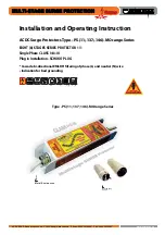
THREE-PHASE POWER SUPPLY
MODEL
MAT2
BEFORE USE ....
Thank you for choosing M-System. Before use, please check
contents of the package you received as outlined below.
If you have any problems or questions with the product,
please contact M-System’s Sales Office or representatives.
■
PACKAGE INCLUDES:
Surge protector ....................................................................(1)
■
MODEL NO.
Check that the model No. described on the specifications
matches the operational line voltage and other specifica-
tions as shown in ‘PERFORMANCE’ hereafter.
■
INSTALLATION / INSTRUCTION MANUAL
This manual describes necessary points of caution when
you use this product, installation, and basic maintenance
procedure.
LIMITATION APPLICABLE TO MAT2
The MAT2 will protect electronics equipment from dam-
age caused by induced lightning by absorbing most of
the surge voltages.
However, MAT2 may not be effective against certain ex-
tremely high voltages exceeding its discharge current
capacity (20 kA or 40 kA @ 8/20µsec. waveform) caused
by a direct or almost direct hit by lightning.
The MAT2 must be installed according to this installa-
tion / instruction manual.
APPLICATIONS
• Protects electric devices such as isolation transformers,
heaters, electromagnetic contactors, motors.
• Protects electric devices of high load current.
• Provides primary protection of a power supply system (L-
L, L-N, and N-PE) in a distribution switchboard.
Low-voltage equipment such as computers, measuring in-
struments, transmission devices, which generally incor-
porates semiconductor circuitries, is especially vulnerable
against lightning surges. We recommend to use combina-
tion type surge protectors incorporating serial impedance
(M-System model examples: MAX, MMA, MAH), or to set
up a double protection by MAT2s (Refer to ‘PROTECTING
LOW-VOLTAGE EQUIPMENT’ under ‘WIRING’ section).
PERFORMANCE
MODEL
Uc
(AC)
(V)
DISCHARGE
VOLTAGE
(Vmin)
Up
(Vmax)
OPERATIONAL
VOLTAGE
RANGE *
1
(50 / 60Hz)
MAT2-240
240
Between
lines:
400 V
N to PE:
550 V
1500
1-phase/2-wire,
3-phase/3-wire:
90 – 240 V AC
1-phase/3-wire:
90 / 180 –
120 / 240 V AC
3-phase/4-wire:
170 – 240 V AC
MAT2-440
440
Between
lines:
780V
N to PE:
550 V
2500
1-phase/2-wire,
3-phase/3-wire:
240 – 440 V AC
1-phase/3-wire:
200 / 400 –
220 / 440 V AC
3-phase/4-wire:
350 – 440 V AC
Uc = Maximum continuous operational voltage
Up = Voltage protection level
*1. MAT2 is operational as an SPD despite the voltage less
than the minimum. However, the functions of the monitor
LED and the alarm output are not guaranteed.
MODEL
MAX. LEAKAGE CURRENT @Uc
ALARM OUTPUT
WITH
WITHOUT
MAT2-240
Line
to
Line
1 to 2
28 mA *
2
6 mA *
3
Other sections
2 mA
2 mA
N to PE
10 µA
10 µA
MAT2-440
Line
to
Line
1 to 2
22 mA
6 mA
Other sections
2 mA
2 mA
N to PE
10 µA
10 µA
*2. Approx. 12 mA @100 V AC
*3. Approx. 3 mA @100 V AC
Discharge current:
MODEL
MAX. DISCHARGE
CURRENT (Imax)
NOMINAL DISCHARGE
CURRENT (In)
MAT2-xM
20 kA (8/20 µsec.)
10 kA (8/20 µsec.)
MAT2-xH
40 kA (8/20 µsec.)
20 kA (8/20 µsec.)
Response time: ≤ 4 nsec. (≤ 20 nsec. for N to PE)
Insulation resistance: ≥ 100 MΩ with 500 V DC (line to alarm
output)
Dielectric strength: 2000 V AC @1 minute (line to alarm
output)