IO-390-D Series Engine Maintenance Manual
74-30
© 2020 Avco Corporation. All Rights Reserved
Page 280
March 2020
IO-390-D Series Engine Maintenance Manual
D.
Examine the
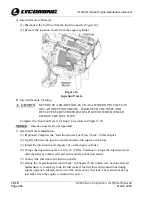
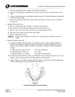
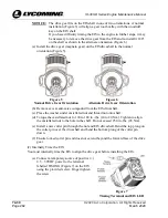
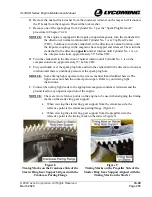
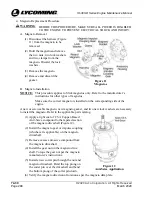
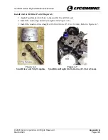
manifold pressure lines (Figure 1)
for cracks, kinks, brittleness, wear, or
damage. Replace any worn, cracked, kinked, damaged, or brittle manifold pressure line.
E.
Examine the manifold pressure lines for security at the fitting in cylinder #3 and at the tee
(Figure 1).
F.
Examine the ignition harness connection to the EIS for general condition and security.
G.
Make sure the Back-Up Battery System is being maintained or inspected in accordance
with its ICA.
H.
Verify the EIS LED blinks out the correct code:
(1)
Ensure the ignition switch is turned off (p-lead grounded).
(2)
Clear the propeller area.
(3)
Turn the ignition switch on (p-lead un-grounded) and verify EIS LED illuminates and
blinks.
NOTICE:
The EIS timing pre-set code is set at the factory and cannot be reset in the
field.
(4)
The EIS LED will blink the code which corresponds with the EIS timing pre-set. The
code will repeat for 4 cycles before the LED goes inactive. Cycle the ignition switch
to see the LED code again. Refer to Table 1 for the correct code for your EIS.
Table 1: EIS Timing Code
Description
LED Code
4 CYL, VARIABLE, ANGLE HEAD
Short-Long-Short-Short
NOTICE:
If the LED blinks rapidly at 12 blinks/second, indicating an internal fault, the
EIS is unairworthy and must be replaced.
I.
Verify both EIS modules are timed correctly to engine #1-cylinder TDC by completing
the EIS Timing Check” in this chapter.
J.
Complete the magneto drop off check per the “Engine Initiation” Chapter in the
IOM-IO-
390-D Series Engine Installation and Operation Manual.
Replace the EIS if engine fails
the magneto drop off check.
2.
EIS Replacement
WARNING
BEFORE STARTING THIS PROCEDURE, MAKE SURE ALL POWER,
INCLUDING THE BACK-UP BATTERY SYSTEM, IS DISABLED TO
THE ENGINE TO PREVENT ELECTRICAL SHOCK AND INJUIRY.
A.
EIS Removal
(1)
Disconnect the ignition leads from all spark plugs.
(2)
Remove one of the spark plugs from Cylinder No. 1 per the “Spark Plug Removal”
procedure in Chapter 74-20.
(3)
Turn the crankshaft in the direction of normal rotation to position the piston in
cylinder #1 at TDC of the compression stroke.
(4)
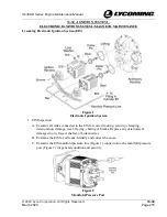
Disconnect the manifold pressure line from the manifold pressure port (Figures 1 and
2).

