LX90xx system Version 4.0
February 2014
Page 19 of 151
4.5.1
Flarm port
1 2 3 4 5 6
Pin numbers
Pin number
Description
1
(output) 12V DC, to supply GPS
2
(output) 3.3V DC (max 100mA)
3
GND
4
Flarm Data Out
5
Flarm Data In
6
Ground
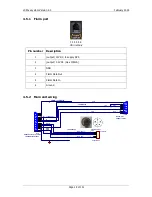
4.5.2
Main unit wiring
1
6
2
7
3
8
4
9
5
SUBD15 Connector / female
LX9000 DIGITAL UNIT
+12V DC OUT
white
red
shield
black
yellow
GND
+12V
B
A
RS485 - OUT
SUBD9 / female
GND
LABEL: +12V DC IN
1
9
2
10
3
11
4
12
5
13
6
14
7
15
8
Data Out
Data In
B
A
1
2
3
4
5
BINDER 5Pin Male
PC-RS232C
09 0097 00 05
White - Data In
Black - Data Out
Shield GND
1
3
5
30 cm
50cm
Red +12V
2
GND
GND
GND
shield
shield
LABEL:RS232
LABEL:RS485
Summary of Contents for LX90xx
Page 2: ......
Page 129: ...LX90xx system Version 4 0 February 2014 Page 129 of 151 ...


