Luxor LE48CWTUD, Installation Manual
The Luxor LE48CWTUD is a sleek and stylish TV that offers incredible picture quality and features. Ensure easy setup and optimal performance by downloading the Installation Manual for free from manualshive.com. This manual provides step-by-step instructions for a hassle-free installation process. Enjoy the ultimate viewing experience with the Luxor LE48CWTUD.
Share
Download


Reviews:
No comments
Related manuals for LE48CWTUD

Junior
Brand: keilhauer Pages: 8

Manchester
Brand: ofichairs Pages: 2

SIGNATURE Series
Brand: nbf Pages: 5

NEX Series
Brand: nbf Pages: 2

GLIDER
Brand: Palmetto Craft Pages: 2

CUBX CBX-CU168
Brand: Target Pages: 12

Theo THW-1L
Brand: Restol Pages: 9

Sonoma Clothes Rack A Frame
Brand: fantastic furniture Pages: 8

Chaise 88 5702 83
Brand: Homestyles Pages: 4

4i
Brand: velda Pages: 20

COFFEETABLE-1
Brand: Youke Pages: 9
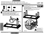
LOF HD
Brand: Canadel Pages: 2

CHARLOTTE S-313SW
Brand: Unfinished Furniture of Wilmington Pages: 5

Bayswater Tallboy 5 Drawer MKII White 24192439
Brand: Freedom Pages: 3

HARBOR
Brand: YOTRIO Pages: 20

Urban BCN PA606
Brand: BENITO Pages: 2

SAFCO TASK MASTER 5113
Brand: LDI Spaces Pages: 6

970393
Brand: ULAX FURNITURE Pages: 7


