2-8
CDD3000-HF Operation Manual
2 Mechanical installation
2.5
Push-through
heat sink (Dx.x)
Step
Action
Comment
1
Mark out the positions of the tapped
holes and the breakthrough on the
backing plate.
Cut a tap for each fixing screw in the
backing plate and cut out the
breakthrough.
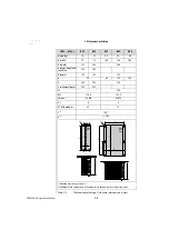
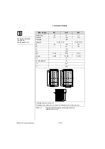
Dimensional drawings/hole
spacing see Table 2.5.
The tapping area will provide you
with good, full-area contact.
2
Mount the drive controller for high-speed
drives
vertically
on the backing plate.
Tighten all screws to the same tightness.
Pay attention to the mounting
clearances! The mounting seal
must contact flush on the surface.
3
Mount the other components, such as the
mains filter, line choke etc., on the
backing plate.
Mains filter max. 20 cm below the
drive controller for highspeed
drives
4
Continue with electrical installation in
section 3.
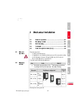
Note the following points:
•
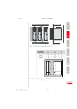
Distribution of power loss:
•
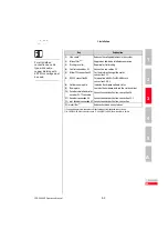
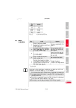
The all-round mounting collar must be fitted with a seal. The seal
must fit flush on the surface and must not be damaged.
(1) Seal
(2) Tapped hole for
EMC contact
(3) Outside
(4) Inside
•
The backing plate must be well grounded.
•
The best result for effective EMC installation is attained with a
chromated or galvanized backing plate. If backing plates are
varnished, the coating must be removed in the area of the contact
surface!
BG3
BG4
BG5
Power loss
Outside (3)
70%
75%
80%
Inside (4)
30%
25%
20%
Protection
Heat sink side (3)
IP54
IP54
IP54
Machine side (4)
IP20
IP20
IP20
;;
yy
;;
yy
(4)
(3)
X5
X6
X7
;
y
(1)
(2)

