background image

1

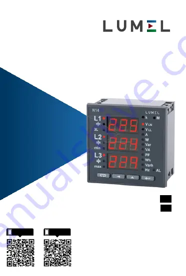
MIERNIK pARAMETRÓW SIECI

NETWORK pARAMETER METER

N14

INSTRUKCJA OBSŁUGI - SZYBKI  START

pełna wersja instrukcji dostępna na

Full version of user’s manual available at  

www.lumel.com.pl

USER’S MANUAl - QUICK START

pl

EN

Zeskanuj mnie

Zeskanuj kod

Scan the code

Summary of Contents for N14

Page 1: ...NETWORK pARAMETER METER N14 INSTRUKCJA OBSŁUGI SZYBKI START pełna wersja instrukcji dostępna na Full version of user s manual available at www lumel com pl USER S MANUAl QUICK START pl EN Zeskanuj mnie Zeskanuj kod Scan the code ...

Page 2: ...dotyczące kompatybilności elektro magnetycznej w środowisku przemysłowym l W instalacji budynku powinien być wyłącznik lub wyłącznik automa tyczny umieszczony w pobliżu urządzenia łatwo dostępny dla ope ratora i odpowiednio oznakowany 2 MONTAŻ Miernik jest przystosowany do zamocowania w tablicy za pomocą uchwytów według rys 1 Obudowa miernika jest wykonana z samogas nącego tworzywa sztucznego Wymi...

Page 3: ...ochodnych automatycznie przeliczane są o wielkość wprowadzonej przekładni zewnętrznego przekładnika Wejścia prądowe określane są w zamówieniu jako 1 A lub 5 A 3 2 Wejścia napięciowe Wielkości na wejściach napięciowych są automatycznie przeliczane o wielkość wprowadzonej przekładni zewnętrznego przekładnika napięciowego Wejścia napięciowe określane są w zamówieniu jako 3 57 7 100 V 3 230 400 V lub ...

Page 4: ...ogramu lub numerem wykonania spe cjalnego Uwaga Jeżeli na wyświetlaczach pojawi się komunikat Err Cal lub Err EE należy skontaktować się z serwisem Uwaga Jeżeli na wyświetlaczach pojawi się komunikat Err L3 L2 należy zamienić podłączenia fazy 2 z fazą 3 Pole wyświetlaczy Pola symboli i jednostek Znacznik załączenia alarmu Przycisk akceptacji Enter Przycisk zwiększania wartości Przycisk zmiany miej...

Page 5: ...5 4 3 Tryby pracy Rys 6 Tryby pracy miernika N14 pl Podane tablice znajdują się w pełnej instrukcji obsługi dostępnej na www lumel com pl ...

Page 6: ...redniania tj 15 minut W przypadku gdy nie upłynie pełny inter wał czasu wyświetlany jest komunikat Err Wyświetlanie błędów opisane zostało w punkcie 8 patrz pełna instruk cja obsługi dostępna na www lumel com pl Załączenie przekaźnika alarmowego sygnalizowane jest podświetle niem znacznika AL Wielkości średnie minimalne maksymalne podświetlone są znaczniki 3L min max Tablica 3 Tablica 2 Dostępne w...

Page 7: ... i przy trzymanie przycisków i przez około 3 sekundy Rys 7 Menu setup Wejście w tryb programowania chronione jest kodem dostępu W przypadku braku kodu pro gram przechodzi w opcje pro gramowania Wyświetlany jest napis SET w pierwszej kolum nie oraz symbole poszczegól nych poziomów P C A pl ...

Page 8: ...zekładnia przekładnika napięciowego 1 4000 oraz t_I przekładnia przekładnika prądowego 1 10000 l l Pobór mocy w obwodzie zasilania 6 VA w obwodzie napiêciowym 0 05 VA w obwodzie pr dowym 0 05 VA Pole odczytowe 3 3 cyfry LED koloru czerwonego wysokoœæ 14 mm Wyjœcie przekaŸnikowe przekaŸnik styki beznapiêciowe zwierne obci alnoœæ 250 V 0 5 A Interfejs szeregowy RS 485 adres 1 247 tryb 8N2 8E1 8O1 8N...

Page 9: ... 2 In 0 0 1 1 2 Un dla wspó czyn ników Pfi t i czêstotliwoœæ 45 65 Hz sinusoidalny THD 8 wspó czynnik mocy 1 0 1 temperatura otoczenia 25 23 55 C temperatura magazynowania 30 70 C wilgotnoœæ 25 95 niedopuszczalne skroplenia dopuszczalny wspó czynnik szczytu natê enia pr du 2 napiêcia 2 zewnêtrzne pole magnetyczne 0 40 400 A m przeci alność krótkotrwa a 5 s wejœcia napiêciowe 2 Un max 1000 V wejœci...

Page 10: ...I 300 V kat III wysokość npm 2000 m MIERNIK PARAMETRÓW SIECI N14 X X XX X Prąd wejściowy In 1 A X 1 1 5 A X 5 2 Napięcie wejściowe fazowe międzyfazowe Un 3 57 7 100 V 1 3 230 400 V 2 3 400 690 V 3 Rodzaj wykonania standardowe 00 napięcie wejsciowe 3 110 190 V 01 specjalne XX Próby odbiorcze bez wymagań dodatkowych 0 z atestami Kontroli Jakości 1 wg uzgodnień z odbiorcą X wykonanie tylko do pomiaró...

Page 11: ...er during the guarantee contract causes its cancellation l The meter fulfils requirements concerning the electromagnetic compatibility in the industrial environment l In the building installation should be a switch or a circuit breaker situated near the meter easy accessible for the operator and suitably marked 2 MOUNTING The meter is adapted to be mounted in a panel by means of holders acc to fig...

Page 12: ... derived quantities are automatically re counted by the quantity of the introduced external transformer ratio Current inputs are defined in the order as 1 A or 5 A 3 2 Voltage inputs Quantities on voltage inputs are automatically recounted by the quantitiy of the introduced external voltage transformer ratio Voltage inputs are defined in the order as 3 x 57 7 100 V 3 x 230 400 V or 3 x 400 690 V L...

Page 13: ... the moment of the start the message Err Cal lub Err EE appears one must contact an authorized service Caution If at the moment of the start the message Err L3 L2 appears on the display one must interchange connec tions of the phase 2 with the phase 3 Fig 5 Message after the meter start 4 N14 PROGRAMMING 4 1 Frontal panel Display field Fields of symbols and units Index of alarm switching on Enter ...

Page 14: ...14 4 3 Working modes Fig 6 Working modes of N14 meter EN The given tables can be found in the full user manual available at www lumel com pl ...

Page 15: ...ll interval of the 15 min mean time In case when the full interval of time is not expired the message Err is displayed The display of errors was described in the chapter 8 see full user s manual available at www lumel com pl The alarm relay switching on is signaled by the AL index backlighting Table 3 Table 2 Basic quantities Markers next to symbols are backlighted Values displayed in row 1 U1 U12...

Page 16: ...n the table 4 Table 4 Measured value Indication range Measuring range Ki Ku 1 L1 Basic error L2 L3 S Current 1 5 A L1 L3 0 00 9 99 kA 0 02 6 A 0 5 Voltage L N Voltage L L 0 0 289 kV 2 9 480 V 0 5 0 0 500 kV 10 830 V 1 l l l 0 2 Frequency 45 0 100 0 Hz 45 0 100 0 Hz Active power Reactive power Apparent power Power factor PF Tangens j 1 2 0 1 2 180 180O 1 0 1 999 MW 0 00 W 999 MW 999 Mvar 0 00 var 9...

Page 17: ...geless NOC contacts load capacity 250 V 0 5A Serial interface RS 485 addres 1 247 mode 8N2 8E1 8O1 8N1 rate 4 8 9 6 19 2 38 4 kbit s Impulse energy output output of O C type passive of class A acc to EN 62053 31 supply voltage 18 27 V current 10 27 mA Impulse constant of the O C type output 5000 imp kWh indepen dently of set Ku Ki ratios Protection degree ensured by the housing from the frontal si...

Page 18: ... position any warm up time 5 min Additional errors in of the basic error from frequency of input signals 50 from ambient temperature changes 50 10 C for THD 8 100 Standards fulfilled by the meter Electromagnetic compatibility noise immunity acc to EN 61000 6 2 interference emission acc to EN 61000 6 4 Safety requirements acc to EN 61010 1 standard isolation between circuits basic installation cate...

Page 19: ...00 690 V 3 Kind of version standard 00 input voltage 3 x 110 190 V 01 custom made XX Additional requirements without an extra quality inspection certificate 8 with a extra quality inspection certificate 7 acc to customer s agreement X Execution only for direct measurement The version code is established by the manufacturer Table 5 6 ORDER CODES EN ...

Page 20: ...0 6 7 9 8 11 1 3 4 2 5 L1 L2 L3 WYimp 15 16 17 19 20 AL 12 14 13 Zasilanie B GNDI N14 A RS485 10 6 7 9 8 11 1 3 4 2 5 WYimp L1 L2 L3 S1 S2 P1 2 S1 S2 P1 P2 P 15 16 17 19 20 AL 12 14 13 Zasilanie B GNDI N14 A RS485 10 6 7 9 8 11 1 3 4 2 5 L1 L2 L3 WYimp 15 16 17 19 20 AL 12 14 13 Zasilanie B GNDI N14 A RS485 10 6 7 9 8 11 1 3 4 2 5 WYimp L1 L2 L3 S1 S2 P1 2 S1 S2 P1 P2 P Direct measurement in a 3 w...

Page 21: ...ych w sieci trójprzewodowej Rys 2 Schematy podłączeń miernika w sieci trójprzewodowej Uwaga W środowisku przemysłowym o dużych zakłóceniach elektromagne tycznych zaleca się uziemić zacisk 11 Indirect measurement with the use of 2 current trans formers and 2 or 3 voltage transformers in a 3 wire network Note In an industrial environment with high electromagnetic noises it is recommended to earth th...

Page 22: ... N S1 S2 P1 P2 S1 S2 P1 P2 S1 S2 P1 P2 15 16 17 19 20 AL 12 14 13 Zasilanie B GNDI A RS485 10 WYimp 15 16 17 19 20 AL 12 14 13 Zasilanie B GNDI N14 A RS485 10 6 7 9 8 11 1 3 4 2 5 WYimp L1 L2 L3 N 15 16 17 19 20 AL 12 14 13 Zasilanie B GNDI N14 A RS485 10 6 7 9 8 11 1 3 4 2 5 WYimp L1 L2 L3 N S1 S2 P1 P2 S1 S2 P1 P2 S1 S2 P1 P2 AL Zasilanie B GNDI A RS485 WYimp Direct measurement in a 4 wire netwo...

Page 23: ... A B a b A B Pomiar pośredni z wyko rzystaniem 3 przekładników prądowych i 2 lub 3 przekładników napięciowych w sieci czteroprzewodowej Rys 3 Schematy podłączeń miernika w sieci czteroprzewodowej Supply OUpulse Indirect measurement with the use of 3 current transformers and 2 or 3 voltage transformers in a 4 wire network Fig 3 Meter connection diagrams in a 4 wire network PL EN ...

Page 24: ...chowska 1 65 022 Zielona Góra Poland tel 48 68 45 75 100 fax 48 68 45 75 508 www lumel com pl Pracownia systemów automatyki tel 68 45 75 228 45 75 117 Wzorcowanie tel 68 45 75 161 e mail laboratorium lumel com pl Export department tel 48 68 45 75 139 45 75 233 45 75 321 45 75 386 45 75 353 fax 48 68 32 54 091 e mail export lumel com pl Calibration Attestation tel 68 45 75 161 e mail laboratorium l...

Reviews: