background image


www.LumaComfort.com 

A

SSEMBLY 

I

NSTRUCTIONS


It is strongly recommended that a second person be available to assist 
during the assembly process. 

DO NOT plug in the fan before assembly. This misting fan comes in three 
separate boxes. Carefully remove all packaging materials and retain for future 
storage/use. Make sure there is no residual foam left in any of the components. 
A screwdriver and wrench will be required to assemble this misting fan. 

S

TEP 

1:


R

EMOVING THE 

W

ATER 

T

ANK


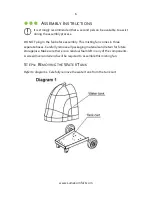
Refer to diagram 1.

 Carefully remove the water tank from the tank cart.


Summary of Contents for Comfort MF26B

Page 1: ...Because you re not like everyone else MISTING FAN MF26B OWNER S MANUAL...

Page 2: ...any questions or concerns regarding your product or if you would simply like to share an idea with us please feel free to contact us Our friendly and knowledgeable customer support team is here for y...

Page 3: ...the Power Supply Upper Back Panel 11 Step 7 Connecting the Power Supply Lower Back Panel 12 Step 8 Connecting the Pump Water Output Hoses 13 Step 9 Locking Unlocking the Handles 14 Operating Instruct...

Page 4: ...uld the grounded plug be altered in any way An improper connection can result in electric shock 8 If possible avoid using extension cords with this misting fan If an extension cord is absolutely neces...

Page 5: ...ing system means no clogged nozzles and no need to use filtered water Fan head constructed of heavy gauge anticorrosive metal for safety and durability Quiet high efficiency fan motor Adjustable misti...

Page 6: ...e assembly This misting fan comes in three separate boxes Carefully remove all packaging materials and retain for future storage use Make sure there is no residual foam left in any of the components A...

Page 7: ...sure not to pull it out by the power cord The water pump will be attached to a metal panel b Position the water pump in an upright position and place it on the plastic beam located at the bottom of t...

Page 8: ...washers flat washers and nuts from the tank cart b Position the stand pole on the tank cart and align the holes on the pole with the four holes on the cart c Using the bolts washers and nuts removed i...

Page 9: ...HEAD a Refer to diagram 4 Remove the fan head from box 1 b Align the stand pole opening on the bottom of the fan head with the stand pole and connect the two pieces together c Use the screw located o...

Page 10: ...rams 5 and 6 Insert the power line that is connected to the fan head into the power line opening and screw in the front panel to the stand pole b Insert the water output hose hose 1 and water input ho...

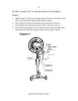
Page 11: ...f the stand pole by unscrewing the 4 M5 screws holding it in place b Insert plug A into socket A and make sure the connection is secure c Insert plug B into socket B and make sure the connection is se...

Page 12: ...8 Place the water tank on the tank shelf b Take the lower back panel that is attached to the pump and locate plug C and socket C Insert plug C into socket C and make sure the connection is secure c R...

Page 13: ...he water tank b Locate the pump hose longer hose the water output hose shorter hose and the pump power cord c On the bottom of the stand pole there are 2 connections one for the water output hose and...

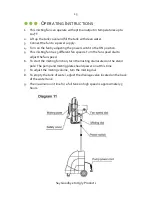
Page 14: ...ed position when first assembled Follow these steps to unlock and lock the handles a Refer to diagram 10 To unlock the handles push the L type pin on the handle joint While pushing in the L type pin s...

Page 15: ...ch to the ON position 5 This misting fan has 3 different fan speeds Turn the fan speed dial to adjust the fan speed 6 To start the misting function turn the misting dial located on the stand pole The...

Page 16: ...int thinner benzene etc as these substances can damage the misting fan Thoroughly dry all of the fan s parts with a soft cloth before reconnecting the unit to a power supply Drain the water tank after...

Page 17: ...lons Fan Speeds 3 RPMs 1400 1500 1700 Noise Levels dB 68 69 72 Temperature Drop 30 45 F Warranty 1 year manufacturer s warranty TROUBLESHOOTING Problem Possible Cause s Possible Solution The fan does...

Page 18: ...of parts that are designed to be replaced such as filters or batteries Power failure and improper power supply such as low voltage defective wiring or inadequate fuses Use of force or damage caused b...

Reviews: