


Lucent Technologies Lineage
®
2000 100A Ferroresonant Rectifier J85503A-1
5 - 12 Installation
Issue 6 October 1998
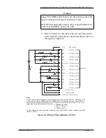
4. Tape or otherwise insulate the connectors on the end of
each cable that does not terminate in the rectifier.
5. Place dc return cable in cable rack.
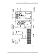
6. Thread end of cable through right side of rectifier and
terminate connector at the appropriate ground bus bar in
the rectifier. The ground bus bar is positive for negative
output voltage plants, and negative for positive output
voltage plants. Torque connection to 120 in-lbs. See Figure
5-2.
7. Remove tape or insulation from connector at other end of
cable and terminate on plant charge ground bus bar.
8. Place dc output cable in cable rack.
9. Thread end of output cable through right side of rectifier
and terminate connector on dc output bus bar in rectifier.
Torque to 120 in-lbs. See Figure 5-2.
10. Remove tape or insulation from connector at other end of
output cable, and terminate connector on (hot) charge bus
bar.
Install Plant
Control Cable
Assembly for a
Lucent
Technologies
Controller
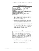
The Plant Control Cable Assembly has a 24-pin or 16-pin
connector on one end and a 40-pin connector on the other end.
The 24-pin or 16-pin end terminates on the battery plant
controller and the 40-pin end terminates on connector P2A of the
CM2 control board located in the rectifier (see Figure 5-2).
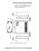
1. Route the plant control cable from the controller chassis
via the cable racks to the rectifier, then through the
opening provided for this cable (see Figure 5-1).
2. Terminate the 40-pin connector on P2A of CM2 and dress
cable (using strain relief bushings and cable ties provided)
inside rectifier allowing for the door to be opened and
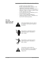
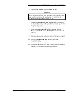
Warning
Avoid arc or sparks. Before making contact between
connectors and the output bus bar in the next step, use a DMM
to verify a true open circuit between connector and known
battery plant ground.