background image


P A D - C L I M A T E - S Y S T E M  

Assembly instruction and operators manual 

Assembly 

17


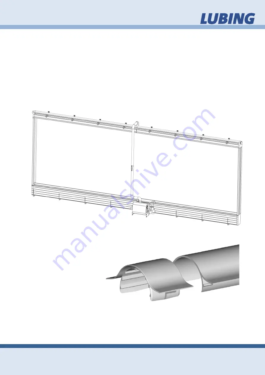
3.7.8.  Covers 

After the demanded drying time of all glue connections press the entire Pad Support 

on the Watergutter. Fasten the Pad Covers with in each case 6 screws evenly over 

the length distributed. For closing the Deflector section set up the Endcover for De-

flector. Glue the Transition Piece at (to) the End(s) and screw the Sealing Cap on the 

Transition Piece. Consider the drying time (24 hours)! 

Push the first Pad into the Pad Cover. Put the other Pad onto the Pad Support. Fas-

ten the Pad  Guide  for each middle element afterwards.  Use to connect the Pad 

Guide to the Pad Guide Coupler. 

Push the last but one Pad into the Pad Cover. Then place the last Pad to the free po-

sition and fasten with the Pad Guide. 


3.7.9.  Deflector 

Clip in the Deflector over the 

whole  length and use the 

Deflector Couplings to con-

nect them. 


Summary of Contents for Pad-Climate-System

Page 1: ...PAD CLIMATE SYSTEM Assembly instruction and operators manual Issue November 2013 Version 1 1 6 ...

Page 2: ...ction and operators manual Introduction 2 Informations obout Producer LUBING Maschinenfabrik GmbH Co KG Lubingstraße 6 49406 Barnstorf Tél 49 0 5442 9879 0 Fax 49 0 5442 9879 33 e mail info lubing de Internet www lubing de Informations obout service ...

Page 3: ...TION IN BUILDING 8 3 2 ASSEMBLY ORDER 9 3 3 SPARE PARTS 9 3 4 RECOMMENDED TOOLS 9 3 5 INSTALLATION PROCEDURES 9 3 6 ASSEMBLING 10 3 7 3 7 1 Bracket for Watergutter 11 3 7 2 Watergutter 12 3 7 3 Glued connections 12 3 7 4 Top Bracket 14 3 7 5 Supply Unit 14 3 7 6 Water Distribution Pipe 15 3 7 7 Pad Guide 16 3 7 8 Covers 17 3 7 9 Deflector 17 4 OPERATING INSTRUCTIONS CONCEPT OF EVAPORATIVE COOLING ...

Page 4: ...ed use of the System The manual contains important notes as the System is to be operated surely properly and economically Their attention helps to avoid dangers to decrease repair costs and down times and to increase the relia bility and the life span of the System The manual is to be supplemented around in structions due to existing national regulations for accident prevention and to envi ronment...

Page 5: ...ngs and symbols 2 1 You will come across the following symbols while reading this manual Warns of general danger Warns of dangerous electrical current Warns of cold Warns of corrosive substances Warns of flammable substances Substances detrimental to health General mandatory sign Mandatory sign indicating protective gloves ...

Page 6: ...erating Instructions include the most important information for operating the Pad Climate Systems in a safe manner The relevant guidelines for the prevention of acci dents as well as other generally recognised technical safety and medical regulations for the workplace must be observed Check that the safety and functional equipment works safely and correctly prior start up at the appropriate interv...

Page 7: ...ganisational measures All safety equipment must be examined at regular intervals Warranty and liability 2 5 As a general rule our General Terms and Conditions Governing Sale and Supply shall apply Warranty and liability claims in the event of personal and material damage are ex cluded if they are attributable to one or more of the following causes non designated use of the Pad Climate system impro...

Page 8: ...o heat concentration with high temperatures which can in turn destroy the equipment and cause fires 3 Assembly Assembly information 3 1 Please read the following pages carefully The instructions in this manual apply for various Pad Climate Systems For this reason we would ask you to select and apply the sections which concern you When using this manual for LUBING standard versions please note all ...

Page 9: ...its item number which we re quire in the event of spare parts being or dered In order to procure electrical compo nents we require information on the power supply e g 230 400 V 3 Ph 50 60 Hz A current version is appended to these As sembly and Operating Instructions Recommended tools 3 5 The following is a list of tools needed for the installation of your LUBING Pad Climate System Tape Measure Hac...

Page 10: ...Ball Valve Pump Cover Top Bracket Elbow Glue Coupler Water Distribution Pipe with holes T Glue Coupler Pipe Connector Pad Guide Deflector Pad Guide Coupler Deflector Coupling Transition Piece Endcover for Deflector Sealing Cap Pad Cover figure 3 7 1 1 3 7 1 2 3 7 1 3 3 7 1 4 3 7 1 5 3 7 1 6 3 7 1 7 3 7 1 8 3 7 1 9 3 7 1 10 3 7 1 11 3 7 1 12 3 7 1 13 3 7 1 14 3 7 1 15 3 7 1 16 3 7 1 17 3 7 1 18 3 7...

Page 11: ... two Brackets for the Supply Unit and those or the last Bracket Then mark with a chalk line the horizontal connection The Supply Unit is already pre assembled The Brackets of the Supply Unit must also been fasted in desired position The uniform load of the ready for use system is 75 kg m 165 lb m Fasten the Brackets in constant distances from max 75 cm 30 in Fasten each Brack et with 3 fasteners a...

Page 12: ...ts in the LUBING product range are designed as glued con nections Please observe the following manufacturer instructions in order to ensure secure connections The pipe must be cut at a right angle and burred The areas to be glued must be clean and dry Clean the ends of the pipe on the outside and the connecting ele ments on the inside using a cleaning agent please check compatibility and woven fel...

Page 13: ... contains tetrahydrofurane and cyclohexanone Xi irritable Irritates the eyes and breathing apparatus Tangit adhesive is highly flammable F easily flammable Tangit is highly inflammable Its solvent vapours are heavier than air and can form explosive mixtures For this reason always ensure sufficient ventilation when pro cessing drying or gluing using Tangit In workrooms and adjoining rooms No smok i...

Page 14: ...g between the Supply Unit and the Water Distribution Pipe Pay attention to straight cuts of the pipe Subsequent ly belve and if necessary clean the front of the pipes Contamination or splinters in the tubing system can reduce the efficiency of the system or cause damage Cut and stick together the whole piping system from the pump to the sump Place the Pump Cover on the Supply Unit for preventing d...

Page 15: ...he Supply Unit Note The holes of the Water Distribution Pipe must stand on 30 degrees with the air flow from the outside Then connect with the pipe connector and the clamps the entire length Pay attention to straight cuts of the pipe Subsequent ly belve and if necessary clean the front of the pipes Contamination or splinters in the tubing system can reduce the efficiency of the system or cause dam...

Page 16: ...d operators manual Assembly 16 3 7 7 Pad Guide Fasten the entire Pad Guide at the wall side through clip in Use the Pad Guide Coupler to connect them over the whole length For closing the Pad Guide Coupler push slider to right and clip in the left Pad Guide ...

Page 17: ...lector Glue the Transition Piece at to the End s and screw the Sealing Cap on the Transition Piece Consider the drying time 24 hours Push the first Pad into the Pad Cover Put the other Pad onto the Pad Support Fas ten the Pad Guide for each middle element afterwards Use to connect the Pad Guide to the Pad Guide Coupler Push the last but one Pad into the Pad Cover Then place the last Pad to the fre...

Page 18: ...gher temperatures during longer periods of time are normal LUBING Pad Climate System comprises the following components Supply Unit Middle elements End kit Prior start up 4 2 Connect the float valve to a suitable water supply WARNING Check to make sure that all locks are secured before each use If needed adjust the floating valve swimmer to the desired water level by turning the adjusting screw Pl...

Page 19: ...If any algae grows tablets need to be added Water pH and chlorine levels should be checked weekly Kits for testing pH and chlo rine may be purchased at any swimming pool supply store The life of your Pad de pends on its proper maintenance Clean the filter at least once a week more often if foreign materials are present in the water system Flush pipe distribution system at least once a month This i...

Page 20: ...son drain the pump sump and pipe system to avoid freezing damage in cold weather If the pump cannot be com pletely drained put anti freeze in it To remove the Pad Guide 4 4 For opening the Pad Guide Coupler push slider to right and clip out the left Pad Guide Malfunctions Trouble shooting 4 5 Problem Reason Solution Pads too dry wet system adjustment follow paragraph 4 2 Prior start up flooded Wat...

Page 21: ...nsity level A 70 dB 1 Max water temperature max 60 C max 140 F Max housing pressure max 2 5 bar Performance 0 45 kW 5 1 2 1 230 V 50 Hz Rated current 3 20 A Weight 7 60 kg 16 8 lb Volumerate 18 m h 4755 gal h 2 5 1 1 1 230 V 60 Hz Rated current 3 20 A Weight 7 60 kg 16 8 lb Volumerate 18 m h 4755 gal h 2 5 1 2 3 Y 400 V 50 60Hz Rated current 1 25 2 1500 A Weight 9 10 kg 20 1 lb Volumerate 18 m h 4...

Reviews: