


315
Learning Advanced Features
Group Code Name
LCD Display Parameter
Setting
Setting
Range
Unit
72
Inverter operation
accumulated time
initialization
Time Reset 0 No
0–1
-
74
Cooling fan operation
accumulated time
Fan time
0/00/00 00:
00
-
min
75
Cooling fan operation
accumulated time
initialization
Fan Time
Reset
0 No
0–1
-
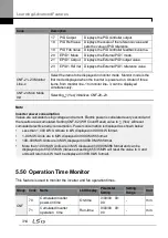
Operation Time Monitor Setting Details
Code
Description
CNF-70 On-time Displays accumulated power supply time. Information is displayed in
[YY/MM/DD Hr: Min (0/00/00 00: 00)] format.
CNF-71 Run-
time
Displays accumulated time of voltage output by operation command input.
Information is displayed in [YY/MM/DD Hr: Min (0/00/00 00: 00)] format.
CNF-72 Time
Reset
Setting ‗1 (Yes)‘ will delete the power supply accumulated time (On-time)
and operation accumulated time (Run-time) and is displayed as 0/00/00 00:
00 format.
CNF-74 Fan time Displays accumulated time of the inverter cooling fan operation. Information
will be displayed in [YY/MM/DD Hr: Min (0/00/00 00: 00)] format.
CNF-75
Fan Time Reset
Setting ‗1 (Yes)‘ will delete the cooling fan operation accumulated time (on-
time) and operation accumulated time (Run-time) and will display it in
0/00/00 00: 00 format.
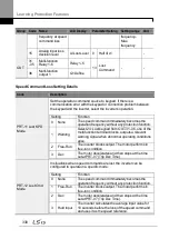
5.51 PowerOn Resume Using the Serial
Communication
If there is a run command when recovering the power after instantaneous power
interruption using serial communication (Serial Communication [BAC net, LonWorks,
Modbus RTU]), the inverter carries out the run command which was set before the
instantaneous power interruption.
Group Code Name
LCD Display
Parameter
Setting
Setting
Range
Unit
Summary of Contents for LSLV0055H100-4COFN
Page 14: ......
Page 18: ...Preparing the Installation 4 37 90 kW 3 Phase ...
Page 27: ...Preparing the Installation 13 ...
Page 47: ...33 Installing the Inverter ...
Page 48: ...Installing the Inverter 34 Input and Output Control Terminal Block Wiring Diagram ...
Page 61: ...47 Installing the Inverter ...
Page 71: ...Learning to Perform Basic Operations 57 ...
Page 88: ...Learning to Perform Basic Operations 74 ...
Page 103: ...89 Learning Basic Features Code Description V1 Quantizing ...
Page 129: ...115 Learning Basic Features ...
Page 140: ...Learning Basic Features 126 ...
Page 148: ...Learning Basic Features 134 ...
Page 171: ...157 Learning Advanced Features Deceleration dwell operation ...
Page 183: ...169 Learning Advanced Features ...
Page 184: ...Learning Advanced Features 170 PID Command Block ...
Page 185: ...171 Learning Advanced Features PID Feedback Block ...
Page 186: ...Learning Advanced Features 172 PID Output Block ...
Page 187: ...173 Learning Advanced Features PID Output Mode Block ...
Page 197: ...183 Learning Advanced Features ...
Page 201: ...187 Learning Advanced Features Code Description 100 EPID1 Control block ...
Page 202: ...Learning Advanced Features 188 EPID2 Control block ...
Page 237: ...223 Learning Advanced Features Time Period Schedule AP3 38 Except3 Day 01 01 ...
Page 244: ...Learning Advanced Features 230 ...
Page 259: ...245 Learning Advanced Features Code Description Code Description Volt ...
Page 362: ...Learning Protection Features 348 ...
Page 415: ...401 RS 485 Communication Features Item Standards Parity check None ...
Page 524: ...Table of Functions 510 ...
Page 533: ...Table of Functions 519 ...
Page 547: ...533 Troubleshooting ...
Page 585: ...Technical Specification 571 ...
Page 594: ...580 ...
Page 595: ...581 ...
Page 596: ...582 ...


