


523
Troubleshooting
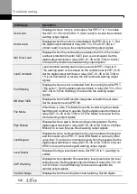
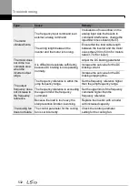
LCD Display
Type
Description
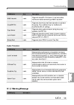
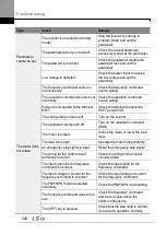
MMC Interlock
Latch
Triggered when AP1-
55 is set to ‗2‘ and all auxiliary
motors are interlocked during an MMC operation.
CleanRPTErr
Latch
Triggered when the pump clean operation is operated
frequently. The conditions may be modified with
theAP2-36
–AP2-37 settings.
Pipe Broken
Latch
Triggered when a pipe is broken during the pump
operation. Set PRT-60.
Level Detect
Latch
Triggered when the inverter output current or power is
lower or higher than the values set by the user. Set the
values at PRT-71
–PRT-77.
Broken Belt
Latch
Triggered when PRT-91 is set to Free Run
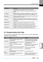
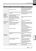
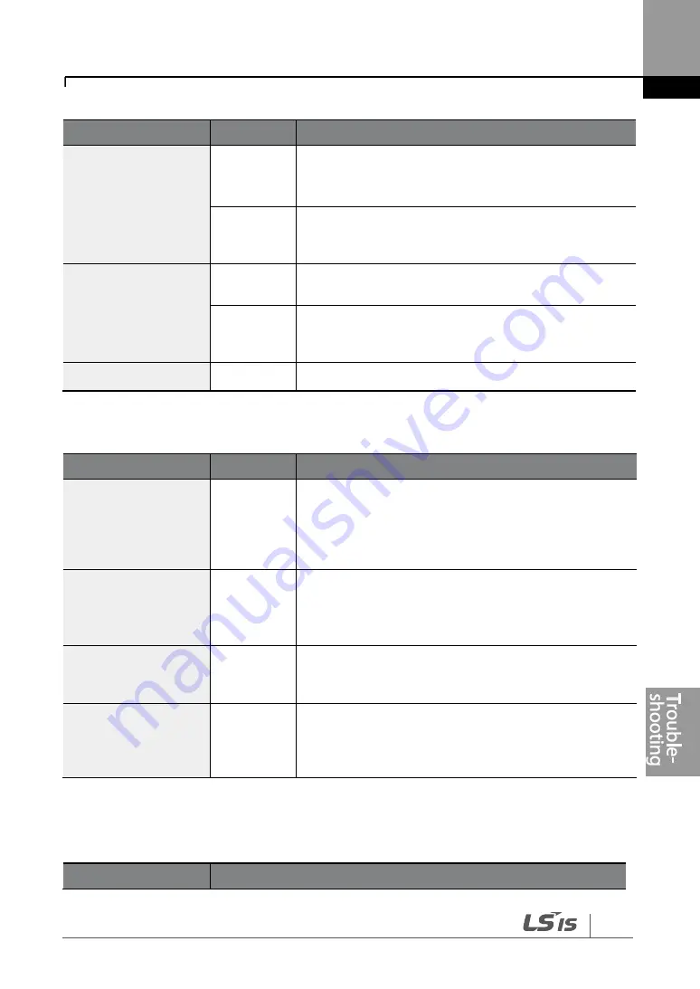
Option Protection
LCD Display
Type
Description
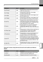
Lost Command
Level
Displayed when a frequency or operation command
error is detected during inverter operation by controllers
other than the keypad (e.g., using a terminal block and
a communication mode). Activate by setting PRT-12 to
any value other than ‗0‘.
IO Board Trip
Latch
Displayed when the I/O board or external
communication card is not connected to the inverter or
there is a bad connection.
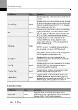
ParaWrite Trip
Latch
Displayed when communication fails during parameter
writing. Occurs due to a control cable fault or a bad
connection.
Option Trip-1
Latch
Displayed when a communication error is detected
between the inverter and the communication board.
Occurs when the communication option card is
installed.
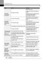
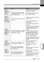
9.1.2 Warning Message
LCD Display
Description
Summary of Contents for H100
Page 14: ......
Page 18: ...Preparing the Installation 4 37 90 kW 3 Phase ...
Page 27: ...Preparing the Installation 13 ...
Page 47: ...33 Installing the Inverter ...
Page 48: ...Installing the Inverter 34 Input and Output Control Terminal Block Wiring Diagram ...
Page 61: ...47 Installing the Inverter ...
Page 71: ...Learning to Perform Basic Operations 57 ...
Page 88: ...Learning to Perform Basic Operations 74 ...
Page 103: ...89 Learning Basic Features Code Description V1 Quantizing ...
Page 129: ...115 Learning Basic Features ...
Page 140: ...Learning Basic Features 126 ...
Page 148: ...Learning Basic Features 134 ...
Page 171: ...157 Learning Advanced Features Deceleration dwell operation ...
Page 183: ...169 Learning Advanced Features ...
Page 184: ...Learning Advanced Features 170 PID Command Block ...
Page 185: ...171 Learning Advanced Features PID Feedback Block ...
Page 186: ...Learning Advanced Features 172 PID Output Block ...
Page 187: ...173 Learning Advanced Features PID Output Mode Block ...
Page 197: ...183 Learning Advanced Features ...
Page 201: ...187 Learning Advanced Features Code Description 100 EPID1 Control block ...
Page 202: ...Learning Advanced Features 188 EPID2 Control block ...
Page 237: ...223 Learning Advanced Features Time Period Schedule AP3 38 Except3 Day 01 01 ...
Page 244: ...Learning Advanced Features 230 ...
Page 259: ...245 Learning Advanced Features Code Description Code Description Volt ...
Page 362: ...Learning Protection Features 348 ...
Page 415: ...401 RS 485 Communication Features Item Standards Parity check None ...
Page 524: ...Table of Functions 510 ...
Page 533: ...Table of Functions 519 ...
Page 547: ...533 Troubleshooting ...
Page 585: ...Technical Specification 571 ...
Page 594: ...580 ...
Page 595: ...581 ...
Page 596: ...582 ...


