215
Learning Advanced Features
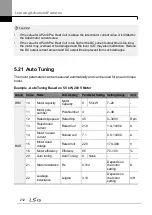
rotation type auto tuning where parameters are measured while the motor is rotating,
parameter values measured with static auto tuning may be less accurate. Inaccuracy of the
measured parameters may degrade the performance of operations. Therefore, run static-
type auto tuning by selecting 2 (All) only when the motor cannot be rotated (when gearing
and belts cannot be separated easily, or when the motor cannot be separated mechanically
from the load).
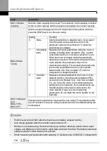
•
If auto tunning operates without wiring the motor,
‗Rs Tune Err‘ or ‗Lsig Tune Err‘ warning
messages are displayed. It can be reset if you press
‗STOP/RESET‘ button of the keypad.
5.22 Time Event Scheduling
Time Event function enables the user to operate the inverter using the RTC (Real-Time
Clock) feature at certain times that the user would like to set. An RTC battery is installed on
the I/O board of the H100 inverter, and it lasts approximately 25,800 hours with the inverter
turned off, and 53,300 hours with the inverter turned on.
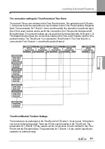
To use the Time Event, set the current date and time. Three parameters need to be set to
configure the Time event feature: Time Period Module, Time Event, and Exception Date.
Time Period
Description
Time Period
Used to set the time of operation.
Time Event
Used to set the time of operation.
Exception Date
Used to specify the exception date. Exception date has the highest
priority.
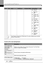
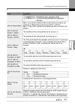
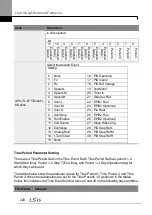
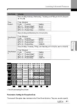
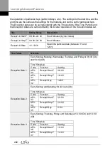
4 Time period Module types, 8 Time Event Module types, and 8 Exception day types can be
used to configure time events. The Time Event function works based on a series of
configuration using the modules listed in the table above.
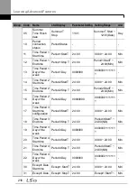
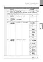
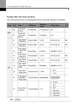
Group Code
Name
LCD Display
Parameter Setting Setting Range
Unit
AP3
01
Current date
Now Date
01/01/2000
01/01/2000 ~
12/31/2099
(Date)
Hz
02
Current time
Now Time
0: 00
0: 00
–23: 59
Sec
03
Current day
of the week
Now Weekday
0000001
0000000
–
1111111
-
04
Summer
Time Start
date
Summer T
Start
04/01
01/01 ~ Summer
T Stop
Day
Summary of Contents for H100
Page 14: ......
Page 18: ...Preparing the Installation 4 37 90 kW 3 Phase ...
Page 27: ...Preparing the Installation 13 ...
Page 47: ...33 Installing the Inverter ...
Page 48: ...Installing the Inverter 34 Input and Output Control Terminal Block Wiring Diagram ...
Page 61: ...47 Installing the Inverter ...
Page 71: ...Learning to Perform Basic Operations 57 ...
Page 88: ...Learning to Perform Basic Operations 74 ...
Page 103: ...89 Learning Basic Features Code Description V1 Quantizing ...
Page 129: ...115 Learning Basic Features ...
Page 140: ...Learning Basic Features 126 ...
Page 148: ...Learning Basic Features 134 ...
Page 171: ...157 Learning Advanced Features Deceleration dwell operation ...
Page 183: ...169 Learning Advanced Features ...
Page 184: ...Learning Advanced Features 170 PID Command Block ...
Page 185: ...171 Learning Advanced Features PID Feedback Block ...
Page 186: ...Learning Advanced Features 172 PID Output Block ...
Page 187: ...173 Learning Advanced Features PID Output Mode Block ...
Page 197: ...183 Learning Advanced Features ...
Page 201: ...187 Learning Advanced Features Code Description 100 EPID1 Control block ...
Page 202: ...Learning Advanced Features 188 EPID2 Control block ...
Page 237: ...223 Learning Advanced Features Time Period Schedule AP3 38 Except3 Day 01 01 ...
Page 244: ...Learning Advanced Features 230 ...
Page 259: ...245 Learning Advanced Features Code Description Code Description Volt ...
Page 362: ...Learning Protection Features 348 ...
Page 415: ...401 RS 485 Communication Features Item Standards Parity check None ...
Page 524: ...Table of Functions 510 ...
Page 533: ...Table of Functions 519 ...
Page 547: ...533 Troubleshooting ...
Page 585: ...Technical Specification 571 ...
Page 594: ...580 ...
Page 595: ...581 ...
Page 596: ...582 ...

