


Learning Advanced Features
158
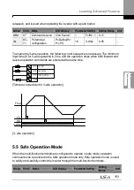
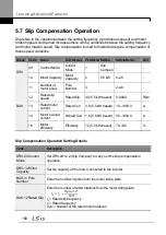
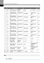
5.7 Slip Compensation Operation
Slip refers to the variation between the setting frequency (synchronous speed) and motor
rotation speed. As the load increases there can be variations between the setting frequency
and motor rotation speed. Slip compensation is used for loads that require compensation of
these speed variations.
Group Code
Name
LCD Display Parameter Setting
Setting Range
Unit
DRV
09
Control Mode
Control
Mode
1
Slip
Compen
-
-
14
Motor Capacity
Motor
Capacity
2
5.5 kW 0
–20
-
BAS
11
Number of
motor poles
Pole
Number
4
2
–48
-
12
Rated slip
speed
Rated Slip
40 (5.5 kW based)
0
–3000
Rpm
13
Rated motor
current
Rated Curr
3.6 (5.5 kW based) 1.0
–1000.0
A
14
Motor no-load
current
Noload Curr 1.6 (5.5 kW based) 0.5
–1000.0
A
16
Motor
efficiency
Efficiency
72 (5.5 kW based)
70
–100
%
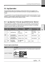
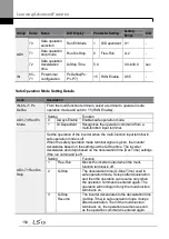
Slip Compensation Operation Setting Details
Code
Description
DRV-09 Control
Mode
Set DRV-
09 to ‗2 (Slip Compen)‘ to carry out the slip compensation
operation.
DRV-14 Motor
Capacity
Set the capacity of the motor connected to the inverter.
BAS-11 Pole
Number
Enter the number of poles from the motor rating plate.
BAS-12 Rated Slip
Enter the number of rated rotations from the motor rating plate.
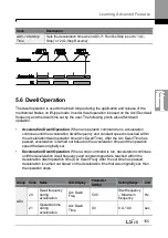
𝑓
𝑠
= 𝑓
𝑟
−
𝑅𝑝𝑚 × 𝑃
120
𝑓
𝑠
= Rated slip frequency
𝑓
𝑟
= Rated frequency
𝑅𝑝𝑚
= Number of the rated motor rotations
Summary of Contents for H100
Page 14: ......
Page 18: ...Preparing the Installation 4 37 90 kW 3 Phase ...
Page 27: ...Preparing the Installation 13 ...
Page 47: ...33 Installing the Inverter ...
Page 48: ...Installing the Inverter 34 Input and Output Control Terminal Block Wiring Diagram ...
Page 61: ...47 Installing the Inverter ...
Page 71: ...Learning to Perform Basic Operations 57 ...
Page 88: ...Learning to Perform Basic Operations 74 ...
Page 103: ...89 Learning Basic Features Code Description V1 Quantizing ...
Page 129: ...115 Learning Basic Features ...
Page 140: ...Learning Basic Features 126 ...
Page 148: ...Learning Basic Features 134 ...
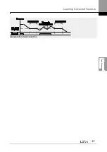
Page 171: ...157 Learning Advanced Features Deceleration dwell operation ...
Page 183: ...169 Learning Advanced Features ...
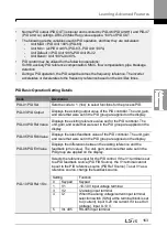
Page 184: ...Learning Advanced Features 170 PID Command Block ...
Page 185: ...171 Learning Advanced Features PID Feedback Block ...
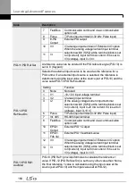
Page 186: ...Learning Advanced Features 172 PID Output Block ...
Page 187: ...173 Learning Advanced Features PID Output Mode Block ...
Page 197: ...183 Learning Advanced Features ...
Page 201: ...187 Learning Advanced Features Code Description 100 EPID1 Control block ...
Page 202: ...Learning Advanced Features 188 EPID2 Control block ...
Page 237: ...223 Learning Advanced Features Time Period Schedule AP3 38 Except3 Day 01 01 ...
Page 244: ...Learning Advanced Features 230 ...
Page 259: ...245 Learning Advanced Features Code Description Code Description Volt ...
Page 362: ...Learning Protection Features 348 ...
Page 415: ...401 RS 485 Communication Features Item Standards Parity check None ...
Page 524: ...Table of Functions 510 ...
Page 533: ...Table of Functions 519 ...
Page 547: ...533 Troubleshooting ...
Page 585: ...Technical Specification 571 ...
Page 594: ...580 ...
Page 595: ...581 ...
Page 596: ...582 ...


