5-8
Signals
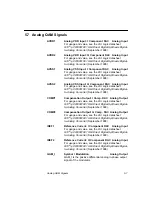
QAM_IN
Symbol I Modulation Inverted
Analog Output
QAM_IN is the corresponding inverted differential part to
QAM_I.
QAM_Q
Symbol Q Modulation
Analog Output
QAM_Q is the positive differential analog quadrature
output signal of the modulator.
QAM_QN
Inverted Differential of QAM_Q
Analog Output
QAM_QN is the corresponding inverted differential part to
QAM_Q.
VDDX_I
Isolated Power: Digital-to-Analog Converter,
I Channel
For usage and value, see the LSI Logic datasheet
G10
®
-p CW900100 10-bit Direct Digital Synthesis Digital-
to-Analog Converter (September 1998).
VDDX_Q
Isolated Power: Digital-to-Analalog Converter,
Q Channel
For usage and value, see the LSI Logic datasheet
G10
®
-p CW900100 10-bit Direct Digital Synthesis Digital-
to-Analog Converter (September 1998).
VREF_I
Reference Voltage Input: I
Analog Input
For usage and value, see the LSI Logic datasheet
G10
®
-p CW900100 10-bit Direct Digital Synthesis Digital-
to-Analog Converter (September 1998).
VREF_Q
Reference Voltage Input: Q
Analog Input
For usage and value, see the LSI Logic datasheet
G10
®
-p CW900100 10-bit Direct Digital Synthesis Digital-
to-Analog Converter (September 1998).
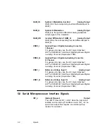
5.8 Serial Microprocessor Interface Signals
INT_n
Interrupt Request
Output
The L64777 asserts INT_n LOW when the interrupt is
enabled and an interrupt condition occurs. INT_n is an
open drain output that requires an external pull-up
resistor for operation.
Summary of Contents for L64777
Page 1: ...L64777 DVB QAM Modulator Order Number I14031 A Technical Manual June 2000...
Page 10: ...x Contents...
Page 14: ...1 4 Introduction...
Page 90: ...5 10 Signals...
Page 110: ...A 8 Programming the L64777 in Serial Host Interface Mode...
Page 116: ...C 2 Monitoring Device Internal Signals...
Page 124: ......

