


3. Wiring Method
3-8
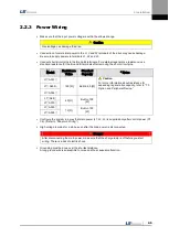
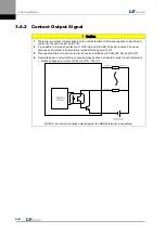
3.4.2
Contact Output Signal
Caution
1.
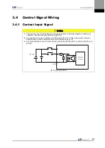
There are two output contacts based on the characteristics of individual signals: contact A and
contact B. They can be set by [P2-10].
4.
It is possible to turn each contact on or off forcibly with [Cn-08]. Take extra caution, however,
because each contact is automatically turned off when power is off.
5.
The signal definition of each contact point can be modified by [P2-05], [P2-06], and [P2-07].
6.
Overvoltage and overcurrent may cause damage because a transistor switch is used internally.
Rated voltage and current: DC 24 [V] ±10%, 150 [
㎃
]
Internal
Circuit
DC 24V
L
L
Contact
Contact
Note 1)
NOTE 1) For alarm and ready output signals, the GND24 terminal is separated.
Summary of Contents for L7 A001
Page 1: ...VER 1 5...
Page 2: ......
Page 32: ...1 Product Components and Signals 1 20...
Page 38: ...2 Installation 2 6...
Page 54: ......
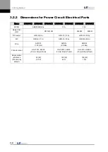
Page 188: ...7 Product Specifications 7 26 L7 A020 L7 A035 Weight 2 5 kg cooling fan included...
Page 210: ...8 Maintenance and Inspection 8 14...
Page 211: ...9 Appendix 9 1 9 Appendix...
Page 218: ...9 Appendix 9 8...
Page 221: ......
Page 222: ......