Safety Precautions
vi
Wiring Precautions
Caution
Be sure to use AC 200-230 V for the input power of the servo drive.
Be sure to connect the servo drive ground terminal.
Do not connect commercial power directly to the servo motor.
Do not connect commercial power directly to the U, V, W output terminal of the servo drive.
Directly connect U, V, W output terminals of the servo drive and U, V, W input terminals of the
servo motor, but do not install a magnetic contactor between the wiring.
Be sure to use a pressurized terminal with an insulation tube when you connect the power
terminal for the servo drive.
When wiring, be sure to separate the U, V, and W cables for the servo motor power and
encoder cable.
Be sure to use robotic cable if the motor requires movement.
Before you perform power line wiring, turn off the input power of the servo drive, and then wait
until the charge lamp goes off completely.
Be sure to use shielded twisted-pair wire for the pulse command signal (PF+, PF-, PR+, PR-),
speed command signal (SPDCOM), and torque command signal (TRQCOM).
Precautions for Initial Operation
Caution
Check the input voltage (AC 200-230 V) and power unit wiring before you turn on the power.
The servo must be in the OFF mode when you turn on the power.
Before you turn on the power, check the motor's ID and the encoder pulse for L7
□
A
□□□
A.
Set the motor ID ([P0-00]) and the encoder pulse ([P0-02]) for L7
□
A
□□□
A first after you
turn on the power.
After you complete the above settings, set the drive mode for the servo drive that is connected
to the upper level controller to [P0-03].
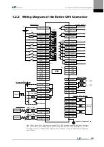
Refer to Chapter 1.2 "System Configuration" to perform CN1 wiring for the servo drive
according to each drive mode.
You can check the ON/OFF state for each input terminal of CN1 at [St-14].
Precautions for Handling and Operation
Caution
Check and adjust each parameter before operation.
Do not touch the rotating unit of the motor during operation.
Do not touch the heat sink during operation.
Be sure to attach or remove the CN1 and CN2 connectors when the power is off.
Extreme change of parameters may cause system instability.
Summary of Contents for L7 A001
Page 1: ...VER 1 5...
Page 2: ......
Page 32: ...1 Product Components and Signals 1 20...
Page 38: ...2 Installation 2 6...
Page 54: ......
Page 188: ...7 Product Specifications 7 26 L7 A020 L7 A035 Weight 2 5 kg cooling fan included...
Page 210: ...8 Maintenance and Inspection 8 14...
Page 211: ...9 Appendix 9 1 9 Appendix...
Page 218: ...9 Appendix 9 8...
Page 221: ......
Page 222: ......


