

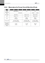

2. Installation
2-2
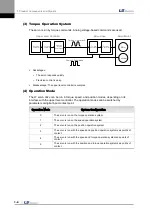
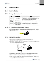
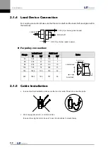
2.1.4
Load Device Connection
For coupling connection: Make sure that the motor shaft and the load shaft are aligned within
the tolerance.
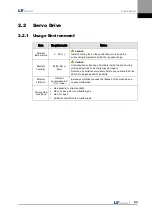
For pulley connection:
Flange
Lateral Load
Axial Load
Notes
N
kgf
N
kgf
40
148
15
39
4
60
206
21
69
7
80
255
26
98
10
130
725
74
362
37
180
1548
158
519
53
220
1850
189
781
90
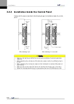
2.1.5
Cable Installation
In case of vertical installation, make sure that no oil or water flows into connection parts.
Do not apply pressure to, or scratch, cables.
In case of moving the motor, be sure to use robotic cables to prevent sway.
Load shaft
Motor shaft
0.03 [
㎜
] or below (peak to peak)
0.03 [
㎜
] or below (peak to peak)
Nr: 30 [
㎜
] or
below
Lateral load
Axial load
Summary of Contents for L7 A001
Page 1: ...VER 1 5...
Page 2: ......
Page 32: ...1 Product Components and Signals 1 20...
Page 38: ...2 Installation 2 6...
Page 54: ......
Page 188: ...7 Product Specifications 7 26 L7 A020 L7 A035 Weight 2 5 kg cooling fan included...
Page 210: ...8 Maintenance and Inspection 8 14...
Page 211: ...9 Appendix 9 1 9 Appendix...
Page 218: ...9 Appendix 9 8...
Page 221: ......
Page 222: ......